


45
• Defrost heat control (DHC) is wired in series in the circuit described above on units
where the supplemental heat is more than would be required to offset the defrost
cooling capacity. Defrost heat control (DHC) is provided on the same models
described above having watt restrictors.
• When the outdoor unit goes into defrost, the circuit between R and W is completed
through a set of contacts on the defrost relay (DR) in series with the contacts on the
defrost heat control (DHC). Purple (PU) pigtails on the indoor unit and outdoor units
must be connected to make circuit. During defrost, the defrost heat control (DHC)
senses the air temperature leaving the indoor unit and cycles the supplemental elec-
tric heat to maintain comfort (75° to 85°) air temperature and prevent objectionable
cold air during defrost. This limits the electric heat output to the minimum required, to
conserve energy and prevent the thermostat from being satisfied with electric heat
and preventing completion of the defrost cycle.
• For most economical operation, if cold air is not of concern during defrost, the purple
wire can be left disconnected. Supplemental heat will only be energized by a call from
second stage room thermostat.
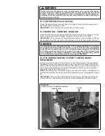
10.5 EMERGENCY HEAT (Heating of Heat Pump)
• If selector switch on thermostat is set to the emergency heat position, the heat pump
will be locked out of the heating circuit, and all heating will be electric heat. Jumper
should be placed between W
2
and E on the thermostat sub-base so that the electric
heat control will transfer to the first stage heat on the thermostat. This will allow the
indoor blower to cycle on and off with the electric heat when the fan switch is in the
auto position.
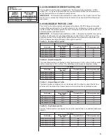
10.6 ROOM THERMOSTAT (ANTICIPATOR SETTING)
See instructions with outdoor section, condensing unit or heat pump for recommended
room thermostats.
• On units with one electric heat sequencer (HR
1
) (see wiring diagram on unit), heat
anticipator setting should be .16.
• On units with two electric heat sequencers (HR
1
& HR
2
) (see wiring diagram on unit),
heat anticipator setting should be .32 if both are connected to same stage on thermo-
stat. Setting should be .16 if (HR
1
&HR
2
) are connected to separate stages.
NOTE:
Some thermostats contain a fixed, non-adjustable heat anticipator. Adjustment is
not permitted.
• The thermostat should be mounted 4 to 5 feet above the floor on an inside wall of the
living room or a hallway that has good air circulation from the other rooms being con-
trolled by the thermostat. It is essential that there be free air circulation at the location
of the same average temperature as other rooms being controlled. Movement of air
should not be obstructed by furniture, doors, draperies, etc. The thermostat should
not be mounted where it will be affected by drafts, hot or cold water pipes or air ducts
in walls, radiant heat from fireplace, lamps, the sun, T.V. or an outside wall. See
instruction sheet packaged with thermostat for mounting and installation instructions.
NOTE:
Some thermostats, particularly solid-state digital types, contain fixed, non-
adjustable heat anticipators and adjustment is not permitted.
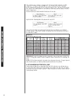
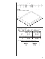
11.0 CALCULATIONS
11.1 CALCULATING TEMPERATURE RISE
• The formula for calculating air temperature rise for electric resistance heat is:
3.16 x Watts
Temperature Rise °F =
CFM
Where: 3.16 = Constant, CFM = Airflow
11.2 CALCULATING BTUH HEATING CAPACITY
• The formula for calculating BTUH heating capacity for electric resistance heat is:
BTUH Heating = Watts x 3.412
Where: 1 kW = 1000 Watts, 3.412 = Btuh/Watt
Содержание RH1V2417STANJA
Страница 54: ...54 FIGURE 44 COMFORT CONTROL2 SYSTEM AIR HANDLER WIRING DIAGRAM H2V...
Страница 55: ...55...
Страница 56: ...56 CM 0115...