


25
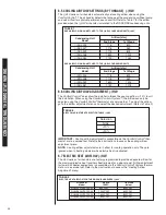
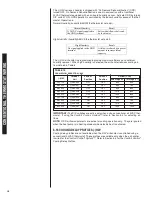
5.2 USING THE ON-BOARD LED TO DETERMINE BLOWER CFM (-)H1V
The (-)H1V interface board LED (see Figure 24) indicates blower output by flashing one (1)
second for every 100 CFM of airflow. The LED will pause 1/10 second between each flash.
After the blower CFM has been displayed, the LED will illuminate dimly for 10 seconds before
repeating the sequence. (See Table 2.)
NOTE:
If airflow is not a multiple of 100 CFM, the last LED flash is a fraction of a second of
100 CFM. (Airflow must be verified, flash code is what is set.)
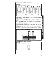
5.3 COOLING AND HEAT PUMP HEATING MODE AIRFLOW SETTINGS (-)H1V
(SEE FIGURE 25)
The (-)H1V-series of air handlers allow a wide range of airflow settings for cooling and heat
pump operation. These airflow settings are selected via DIP switches 1 and 2 on the interface
board. DIP switches 1 and 2 allow the user to tailor the airflow for the particular installation.
NOTE:
Cooling/heating air-flow adjustments using DIP switches 3 and 4 also affect electric
heat airflow on (-)H1V air-handlers.
TABLE 2
LED FLASH CODES
INTERFACE
BOARD
DIP SWITCH
SETTINGS
1200 CFM
600 CFM
950 CFM
SOME EXAMPLES OF
LED OUTPUT
• Flashes 12 times
• Illuminate dimly 10 seconds, repeat sequence
• Flashes 6 times
• Illuminate dimly 10 seconds, repeat sequence
• Flashes 9 times, flash once for
1
/
2
second
• Illuminate dimly 10 seconds, repeat sequence
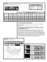
FIGURE 24
IFC BOARD
LED
FUSE
Содержание RH1V2417STANJA
Страница 54: ...54 FIGURE 44 COMFORT CONTROL2 SYSTEM AIR HANDLER WIRING DIAGRAM H2V...
Страница 55: ...55...
Страница 56: ...56 CM 0115...