


3.4 INSTALLATION IN AN UNCONDITIONED SPACE
The exterior cabinet of an air handler has a greater risk of sweating when installed in an
unconditioned space than when it is installed in the conditioned space. This is primarily
due to the temperature of the conditioned air moving through the air handler and the air
circulating around the unit where it is installed. For this reason, we recommend the fol-
lowing for all air handler applications, but special attention should be paid to those
installed in unconditioned spaces:
• Duct sizing and airflow are critical and based on the equipment selected
• Supply and return duct attachment: If other than the factory flanges are used, the
attachment of ducting must be insulated and tight to prevent sweating.
• No perimeter supply flanges are provided. If a full perimeter supply duct is used, it is
the responsibility of the installer to provide duct flanges as needed, to secure and seal
the supply duct to prevent air leakage and the sweating that will result.
• All wire penetrations should be sealed. Take care not to damage, remove or com-
press insulation in those cases.
• In some cases, the entire air handler can be wrapped with insulation. This can be
done as long as the unit is completely enclosed in insulation, sealed and service
access is provided to prevent accumulation of moisture inside the insulation.
• As required, use a secondary pan that will protect the structure from excessive sweat-
ing or a restricted coil drain line.
• If a heater kit is installed, be sure the breaker or disconnect cover is sealed tightly to
the door panel.
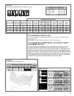
3.5 INSTALLATION IN MOBILE/MANUFACTURED HOMES
1. Air handler must be secured to the structure using “L” brackets or pipe strap.
2. Allow a minimum of 24 inches (610 mm) front clearance required to access doors.
3. Recommended method for securing air handler:
A. If air handler is against the wall, secure top of air handler to wall stud using two
16ga thick angle brackets one on each side. Attach brackets with No. 10 self-tap-
ping
1
⁄
2
long screws to air handler and use
5
⁄
16
lag screws 1
1
⁄
2
long to wall stud.
Secure bottom of unit with two 16ga “L” brackets with No. 10 self-tapping
1
⁄
2
long
screws to air handler and use
5
⁄
16
lag screws 1
1
⁄
2
long to floor.
FIGURE 7
INDOOR COIL AND DRAIN PAN SET-UP
ST-A1213-01
HORIZONTAL ADAPTER
KIT
TOP AIR STOP
STRAPS
VAPOR LINE
CONNECTION
PRIMARY
DRAIN
CONNECTION
LIQUID LINE
CONNECTION
VERTICAL
DRAIN PAN
AUXILIARY
HORIZONTAL
DRAIN
CONNECTION
AUXILIARY
UPFLOW/DOWNFLOW
DRAIN CONNECTION
12
Содержание RH1V2417STANJA
Страница 54: ...54 FIGURE 44 COMFORT CONTROL2 SYSTEM AIR HANDLER WIRING DIAGRAM H2V...
Страница 55: ...55...
Страница 56: ...56 CM 0115...