


27
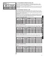
5.6 COOLING DELAY PROFILES (-)H1V
The (-)H1V air handlers are shipped with a default 30 second blower OFF delay profile for
maximum efficiency.
IMPORTANT:
Blower
ON
delay profiles are not used in heating mode.
5.7 COOLING MODE DEHUMIDIFICATION (-)H1V (PASSIVE: FACTORY
PROGRAMMED PROFILES)
Factory board settings will provide general overall performance under average conditions.
Use these Advanced Profiles to optimize performance and to add soft motor operation.
Please be sure that you check for correct airflow and adjust refrigerant charge based on your
Maximum Capacity and Airflow using the Factory AIRFLOW SETTINGS. Switches 1 and 2
should be set for the tonnage and airflow requirement for the system.
Advanced Airflow set-
tings
will, in most cases, greatly reduce airflow to the system and change the system’s Latent
and Sensible capacity splits. The control board flashes CFM to the nearest 50 CFM calculat-
ed.
We suggest that trouble-shooting be done with switches in the factory position for
verification of refrigerant charge and airflow through the duct system.
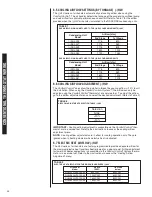
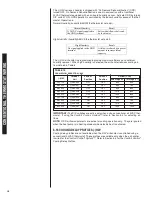
TABLE 3 (-)H1V
S8
S7
S7
S8
On
On
Off
On Off
Ramp Times
CFM Reduction
5 minutes
18% Less
5 to 12.5 minutes
12% Less
after 12.5 minutes
100% Full
Operating
Sequence
Pre-programmed CFM Rates
Ramp Times
CFM Reduction
3 minutes
18% Less
after 3 minutes
100% Full
Operating
Sequence
Pre-programmed CFM Rates
Ramp Times
CFM Reduction
3 minutes
25% Less
3 to 8 minutes
12% Less
after 8 minutes
100% Full
Operating
Sequence
Pre-programmed CFM Rates
Off
S7
S8
FIGURE 28
COOLING AIRFLOW ADJUSTMENTS (-)H1V
Factory
S7
on
off
on
off
S8
off
on
on
off
Moisture
Removal
Highest
Advanced Cooling Adjustments
Switch 7 and 8 Settings and Characteristics
Standard
Lowest
Good
A
OFF
OFF
800
1200
1200
1600
1800
1800
1725
B
ON
OFF
600
600
600
800
800
800
800
C
OFF
ON
800
1000
1000
1400
1600
1600
1600
D
ON
ON
600
600
600
800
800
800
800
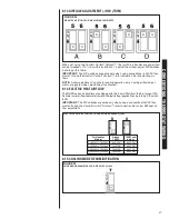
FIGURE 27
FACTORY AIRFLOW SETTINGS FOR SWITCHES 5 AND 6 (-)H1V
SELECTION
SWITCH 5
POSITION
SWITCH 6
POSITION
(-)H1V-
2417ST
(-)H1V-
3617ST
(-)H1V-
3821ST
3621H
(-)H1V-
4824ST
4821M
(-)H1V-
4824ST
(-)H1V-
6024ST
(-)H1V-
6021S
ELECTRIC HEAT AIR FLOW
O
N
O
N
O
N
O
N
A
B
C
D
5
6
5
6
5
6
5
6
MINIMUM AIR FLOW PER kW
3 kW to 13 kW
=
600 min. CFM
15 kW to 18 kW
=
800 min. CFM
20 kW to 25 kW
=
1400 min. CFM
30 kW
=
1800 min. CFM
Содержание RH1V2417STANJA
Страница 54: ...54 FIGURE 44 COMFORT CONTROL2 SYSTEM AIR HANDLER WIRING DIAGRAM H2V...
Страница 55: ...55...
Страница 56: ...56 CM 0115...