SNAP2411
SNAP2411
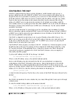
Figures 1 and 2 identify the various connectors and indicators of the SNAP2411.
Figure 1. SNAP2411 Front Panel Diagram
LINK
TXD RXD
LINK
RF
ETHERNET
PWR
S N A P 2 4 11
Figure 2. SNAP2411 Rear Panel Diagram
DC IN
ETHERNET
SYNC OUT
SYNC IN
CONSOLE
RF OUT
The antenna connector is a reverse polarity TNC type connector. An antenna may be connected
directly to this connector. Alternatively, an antenna may be located away from the SNAP using
RF cable to connect the SNAP to the antenna. Cirronet does not recommend using RF cables
longer than 5 feet. If more distance is required between the SNAP and the antenna Cirronet
recommends using the SNAP2411X. If the SNAP2411X is not used, high-quality, low-loss RF
feed line must be used.
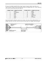
The 10/100BaseT Ethernet connector is the standard RJ-45 connector. The connector is wired to
be able to connect directly to an Ethernet hub using a cross-over cable. If it is desired to connect
the SNAP directly to a PC without a hub, the SNAP must be connected with a straight through
cable. (Both cables are provided.)
©
2000- 2004 Cirronet
™
Inc
3
M-2411-0012 Rev -


