SNAP2411
Attaching the Data/Power Cable Connector
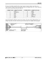
The figure below shows the pin numbering of the Data/Power connector. The view provided is looking into the side
of the connector into which the pins will be inserted.
The cable pins are installed by choosing the appropriate conductor color and connector hole location and inserting
the pin into the hole until it “clicks” into place. Verify the pin is locked into place by gently pulling on the
conductor.
If a pin is installed in the wrong connector location, use the extractor tool to remove the pin. Insert the extractor tool
into the connector hole such that the tool surrounds the pin. Gently push the extractor tool completely into the hole.
Remove the pin by gently pulling on the conductor. If the pin does not come out easily, it is an indication the tool is
not fully inserted. Do not pull on the conductor forcefully as that can pull the conductor out of the pin.
Use the following color code to insert the pins into the connector:
C
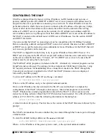
ONNECTOR
P
IN
C
ONDUCTOR
C
OLOR
C
ONNECTOR
P
IN
C
ONDUCTOR
C
OLOR
1 Brown
9 Green
2 Orange/Black
10 Orange
3 Black
11 Violet
4 Blue
12 Yellow
5 Tan
13 White/Black
6 Pink
14 Grey
7 White
15 White/Red
8 Red
Care must be taken to follow the color code correctly. An incorrectly assembled connector can damage the radio or
the card or both.
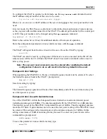
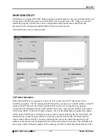
Complete the assembly by placing the connector in the slot in one of the shell halves. Install the two retaining
screws on both sides of the shell and through the holes on both sides of the connector; place the other shell half over
the connector so the connector lies in the shell slot. Secure the connector shell halves with the nuts and bolts
provided.
Refer to the figures below.
Pinned connector in bottom connector shell
Completed connector with top connector shell attached.
©
2000- 2004 Cirronet
™
Inc
7
M-2411-0012 Rev -


