7
SSCBL-RPBL-IOM (10-22) 149159-C
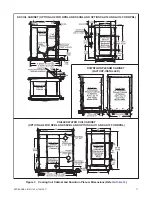
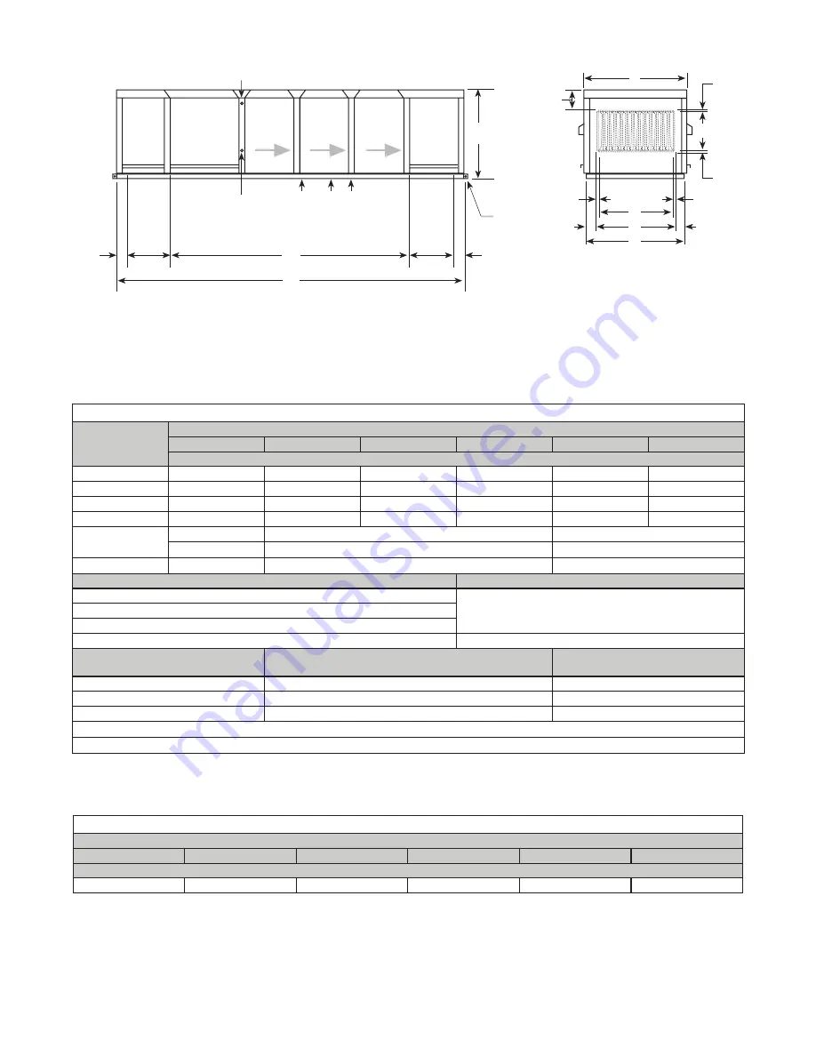
Figure 2. RPBL Dimensions (Refer to
)
Table 3. RPBL Dimensions
Dimension
(See
)
Unit Size
400
500, 600
700
800
1050
1200
Inches (mm)
A
58-7/8 (1495)
47-1/8 (1216)
53-3/8 (1356)
58-7/8 (1495)
53-3/8 (1356)
58-7/8 (1495)
B
47-5/8 (1210)
36-5/8 (930)
42-1/8 (1070)
47-5/8 (1210)
42-1/8 (1070)
47-5/8 (1210)
C
56-1/8 (1426)
45-1/8 (1146)
50-5/8 (1286)
56-1/8 (1426)
50-5/8 (1286)
56-1/8 (1426)
D
45-1/2 (1156)
34-1/2 (876)
40 (1016)
45-1/2 (1156)
40 (1016)
45-1/2 (1156)
E
83-3/4 (2127)
109-3/4 (2788)
135-3/4 (3448)
107-3/4 (2737)
*
133-3/4 (3397)
*
159-3/4 (4058)
*
F
60-5/16 (1532)
*
86-5/16 (2192)
*
112-5/16 (2853)
*
Air Opening (See
)
Inches (mm)
Standard horizontal air inlet opening
19-1/2 (495) × B
Optional return air opening (bottom)
Optional discharge air opening with downturn plenum
Standard horizontal discharge air opening
18 (457) × D
Gas Connection Location
**
(See
)
Approximate Distance from Inside Curb Cap
on Blower End of System
Unit Size
1
89–90 inches (2261–2286 mm)
400
2
103–104 inches (2616–2642 mm)
500, 600, 700, 800
3
110–111 inches (2794–2819 mm)
1050, 1200
*
With downturn plenum (option AQ5 or AQ8) .
**
The gas connection is at curb cap height on the control side of the system .
Weights
Table 4. Weights
Unit Size
400
500, 600
700
800
1050
1200
Net Weight (Pounds (kg))
849 (385)
1104 (500)
1184 (537)
1245 (565)
1476 (670)
1565 (710)
FRONT VIEW
(STANDARD HORIZONTAL DISCHARGE)
LEFT SIDE VIEW
CONTROL CONN
ELECTRIC CONN
GAS CONNS
FURNACE
AIRFLOW
BLOWER
CABINET
CURB
CAP
OPTIONAL RETURN AIR OPENING
OPTIONAL SUPPL
Y AIR
OPENING
4-3/32
(104)
19-1/2
(495)
19-1/2
(495)
3/4
(19)
3/4
(19)
3/4
(19)
3/4
(19)
4-1/4
(108)
4-1/4
(108)
4-3/32
(104)
8-15/32
(215)
40-1/8 (1019)
F
E
D
B
C
OPTIONAL DO
WNTURN
PLENUM
(2) (3)
(1)
18 (457)
A
FURNACE
FURNACE
AIRFLOW
AIRFLOW
NOTES:
Inches (mm)
Burner and control access shown left-hand side. Specify right-hand side for opposite access and connections.


