background image

DIAX04 ELS-06VRS

Description of Diagnostic Letters F... and E... 

4-17

DOK-DIAX04-ELS-06VRS**-WA01-EN-P           

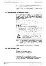
On 2:  Increase cycle time, reduce the speed of the drive, install

additional bleeder.

On 3:

Replace unit.

 F360 Overcurrent power supply unit

With HVR only!

Cause:

Short-circuit in power supply unit, drive controller, motor or a cable.

Remedy:

Disconnect power supply lines on the drive controller one at a time.
Replace a unit if it is defective.

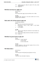
 F369 +24V/+-15V/+5V fault power supply unit

Control voltage interference.

Cause:

1.

Maximum permissible load has been exceeded

2.

Short-circuit in wiring if control voltage is used outside
of drive system.

3.

Unit is defective.

Remedy

On 1:

Remove control voltage bus connections to drive controllers one
after the other.

On 2:

Remove control voltage connections and check for short-circuits.

On 3:

Replace unit.

 F380 Short to ground power supply unit

Cause:

Ground short:  in power supply unit

in drive controller

in motor or motor cable

Remedy:

Remove connections to motor and power supply unit one at a time.
Replace defective drive components.

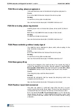
 F381 Mains failure

With HVR only !

Cause:

At least one phase of the 3 phase power supply input is missing.

Remedy:

Check mains fuses and replace, if necessary.

Содержание DIAX04

Страница 1: ...Troubleshooting Guide ELS 06VRS DOK DIAX04 ELS 06VRS WA01 EN P SYSTEM200 DIAX04 Drive With Electric Gear Function...

Страница 2: ...rs and the use or communication of the contents thereof without express authority are forbidden Offenders are liable for the payment of damages All rights are reserved in the event of the grant of a p...

Страница 3: ...unction based on SERCOS Parameters Parameter Description A description of all parameters used in the firmware Troubleshooting Guide Explanation of the diagnostic states How to proceed when eliminating...

Страница 4: ...About this Documentation DIAX04 ELS 06VRS DOK DIAX04 ELS 06VRS WA01 EN P Notes...

Страница 5: ...V 3 6 3 7 Protection Against Dangerous Movements 3 7 3 8 Protection Against Magnetic and Electromagnetic Fields During Operation and Mounting 3 9 3 9 Protection Against Contact with Hot Parts 3 10 3 1...

Страница 6: ...4 14 F281 Mains fault 4 15 F282 Phase loss fault 4 15 F283 Line voltage fault 4 15 F284 Main contactor off low voltage 4 15 F285 Mains current limit 4 15 F316 Softstart fault power supply unit 4 16 F...

Страница 7: ...tage in power section 4 30 E247 Interpolation velocity 0 4 30 E248 Interpolation acceleration 0 4 30 E249 Positioning velocity S 0 0091 4 31 E250 Drive overtemp prewarning 4 31 E251 Motor overtemp pre...

Страница 8: ...r 5 6 C114 T4 TScyc S 0 0002 T4min S 0 0005 5 6 C115 T2 too small 5 7 C200 Communication phase 4 transition check 5 7 C201 Invalid parameter s S 0 0022 5 7 C202 Parameter limit error S 0 0022 5 7 C203...

Страница 9: ...D300 Command adjust commutation 5 20 D301 Drive not ready for commutation command 5 20 D500 Command Get mark position 5 20 D501 Incremental encoder required 5 21 D600 Cancel reference point procedure...

Страница 10: ...A147 Relative drive controlled interpolation encoder 2 5 30 A148 Relative drive contr interpolation enc 1 lagless 5 30 A149 Relative drive contr interpolation enc 2 lagless 5 31 A800 Unknown operating...

Страница 11: ...status Construction of a Diagnostic Message A diagnostic message consists of A diagnostic number and a diagnostic text F228 Excessive Control Deviation Diagnostic message number Diagnostic message Fig...

Страница 12: ...y Fig 1 2 H1 and H2 displays on the HDS and HDD controllers The diagnostic number appears on this two positional seven segment display The image can be seen on the Diagnostic Message Priority Display...

Страница 13: ...or Command active Ready to operate Drive ready Drive stop Drive is following operating mode Fig 1 3 Diagnostic message priority diagram Clear Coded Diagnostic Message The clear coded diagnostic messag...

Страница 14: ...1 4 Diagnostic Message Descriptions DIAX04 ELS 06VRS DOK DIAX04 ELS 06VRS WA01 EN P Notes...

Страница 15: ...s the guarantee and the right to payment of damages resulting from inappropriate use are forfeited The user alone carries all responsibility of the risks Before using Rexroth Indramat products make su...

Страница 16: ...o ensure an application specific use the drive controllers are available with differing drive power and different interfaces Typical applications of drive controllers are handling and mounting systems...

Страница 17: ...e person or persons responsible for the safe operation of this equipment If the equipment is resold rented or transferred or passed on to others then these safety instructions must be delivered with t...

Страница 18: ...s WARNING High electrical voltage due to wrong connections Danger to life or bodily harm by electric shock WARNING Health hazard for persons with heart pacemakers metal implants and hearing aids in pr...

Страница 19: ...ts and accessories approved by the manufacturer Follow all safety regulations and requirements for the specific application as practiced in the country of use The equipment is designed for installatio...

Страница 20: ...structions for installation in accordance with EMC requirements can be found in the documentation EMC in Drive and Control Systems The machine or installation manufacturer is responsible for complianc...

Страница 21: ...even for brief measurements or tests if the ground wire is not permanently connected to the points of the components provided for this purpose Before working with electrical parts with voltage higher...

Страница 22: ...onductor connection Prior to startups even for brief tests always connect the protective conductor or connect with ground wire Otherwise high voltages can occur on the housing that lead to electric sh...

Страница 23: ...onents software or firmware errors Dangerous movements can occur immediately after equipment is switched on or even after an unspecified time of trouble free operation The monitoring in the drive comp...

Страница 24: ...ist maximum possible momentum especially if there is a possibility of loose parts flying off Mount the emergency stop switch in the immediate reach of the operator Verify that the emergency stop works...

Страница 25: ...ing conductors and permanent magnets in motors represent a serious health hazard to persons with heart pacemakers metal implants and hearing aids WARNING Health hazard for persons with heart pacemaker...

Страница 26: ...unting Under certain conditions incorrect handling and mounting of parts and components may cause injuries CAUTION Risk of injury by incorrect handling Bodily harm caused by crushing shearing cutting...

Страница 27: ...s corresponding to the information in the respective Project Planning Manual must be provided with pressurized media such as compressed air hydraulic oil cooling fluid and cooling lubricant supplied b...

Страница 28: ...3 12 Safety Instructions for Electric Drives and Controls DIAX04 ELS 06VRS DOK DIAX04 ELS 06VRS WA01 EN P Notes...

Страница 29: ...celeration Non fatal F2xx In accordance with Best possible deceleration Fig 4 1 Error classes and drive reaction If an error state is detected in the drive then an automatic operation of the drive s e...

Страница 30: ...ck on the motor After powering up the drive compares the motor type stored in the parameter with the connected motor type If the motor types do not match basic control loop settings must be adapted to...

Страница 31: ...or to shutdown of unit For Remedy 1 Reduce the ambient temperature e g through cooling of the control cabinet 2 Remove obstructions or dirt from the heatsink 3 Install the device vertically and clear...

Страница 32: ...g signals MT emp and MT emp for interruption and short circuit See also the functional description Temperature monitoring F226 Undervoltage in power section The level of the DC bus voltage is monitore...

Страница 33: ...t parameter values set in the drive parameters 4 Incorrect parameter values in S 0 0159 Monitoring window Remedy Ref 1 Check the S 0 0092 Bipolar torque force limit value parameter and set it to the m...

Страница 34: ...ic operation phase 4 the position feedback difference of both encoders is compared with S 0 0391 Monitoring window feedback 2 If the amount of the difference exceeds the monitoring window the error F2...

Страница 35: ...ccessive position command values is greater than or equal to the value in S 0 0091 Bipolar velocity limit value position command value monitoring is initiated The Excessive position command value is s...

Страница 36: ...ified to the nominal pointer length of 0 5V 13 3 6 65V DLF and output With the corresponding setting X Y operation of the oscilloscope you will obtain the following signal shape Permissible signal amp...

Страница 37: ...the encoder cable 2 Keep the encoder cable well away from power cables 3 Exchange the encoder interface F248 Low battery voltage Cause For motors of series MKD and MKE the absolute position informatio...

Страница 38: ...als of the master encoder are monitored If its signal amplitude falls below a minimum threshold value then this error message appears The drive performs the best possible deceleration as selected in t...

Страница 39: ...his does not clear the error note the number of lines use P 0 0502 and traversing speed at which error occurred and call Indramat customer service See function description Functional principle Increme...

Страница 40: ...of the drive controller is required Remedy For 1 Check the power supply For 2 Check the motor cable For 3 Exchange the motor For 4 Exchange the drive controller See also the functional description Mot...

Страница 41: ...Activation and Polarity F272 Error power supply probe input The probe inputs of the DSS2 1 plug in module require an external 24 V power supply The drive monitors the external 24 V power supply if the...

Страница 42: ...sition 2 The axis was moved while turned off and sits outside of its permissible position Check to see if the displayed position is correct in relation to the machine zero point Then reset the error 3...

Страница 43: ...ck Cause A power supply phase has failed or is outside of the permissible tolerance Remedy Check the power supply connection according to the project planning specifications of the drive controller be...

Страница 44: ...e returns If so exchange the drive otherwise continue by connecting one drive at a time until the defective unit is determined Once the defective unit is determined exchange it 2 The number of additio...

Страница 45: ...1 Maximum permissible load has been exceeded 2 Short circuit in wiring if control voltage is used outside of drive system 3 Unit is defective Remedy On 1 Remove control voltage bus connections to driv...

Страница 46: ...matching transformer if necessary F384 Connection error at power supply unit With HVR only Cause Power and control voltage connects are not in phase Remedy Check connection voltage Terminals X5 U and...

Страница 47: ...Fieldbus bus connection terminated blocked longer than watchdog duration 5 The bus master is no longer sending cyclic telegrams to the drive although they are expected in phase 4 Remedy for 1 All fibe...

Страница 48: ...trol system manufacturer See also the functional description SERCOS interface error F434 Emergency Stop Pressing the emergency stop switch E Stop has caused the drive to perform the emergency stop fun...

Страница 49: ...h the error response Set velocity command value to zero Bit 2 of paramater P 0 0090 Travel limit parameter is set for Exceeding travel range is an error or after exceeding the position limit a drive c...

Страница 50: ...ange Note The drive will not accept command values which lead out of the permissible travel range Entering these command values in the drive controller will result in this error See also the functiona...

Страница 51: ...tion analysis of that measurement system These are monitored according to two criteria 1 The pointer length which is calculated from the amplified sine and cosine signals must be 5 V while the encoder...

Страница 52: ...5 V V 9 2 6 5V 6 5V length pointer 2 2 Note The error cannot be cleared in communications phase 4 Before clearing the error switch to communications phase 2 Note When an incremental encoder with squar...

Страница 53: ...rrent regulator was parameterized with wrong values Remedy For 1 Check the motor cable for a short For 2 Exchange the drive controller For 3 Check that the current controller parameters are as given i...

Страница 54: ...a short circuit Note This error can only be cleared in parameter mode phase 2 As a result of this error the encoder emulation is switched off F871 10Volt DC error The power supply voltage for the cur...

Страница 55: ...old value or a minimum of 100 rpm rotary motor or by 100 mm min linear motor Cause The torque command value was for too long a time greater than the load torque This causes the actual speed to increas...

Страница 56: ...code of current measuring unit A faulty current measuring unit was discovered after the control voltage was turned on Cause The current measuring unit has an incorrect code The coding does not work w...

Страница 57: ...terwards the drive controller will be brought to a standstill according to the selected error response and message F221 Error Motor temp surveillance defective will be generated Cause 1 Motor temperat...

Страница 58: ...controlled homing jog drive halt The E247 warning is issued if the employed velocity specification is 0 Possible velocity specifications are S 0 0259 Positioning velocity S 0 0041 Homing velocity S 0...

Страница 59: ...edy S 0 0259 Positioning Velocity or P 0 4030 Jog velocity must be reduced See also functional description Operating Mode Drive Internal Interpolation E250 Drive overtemp prewarning The temperature of...

Страница 60: ...peration of cooling system clean air ways See also the functional description Temperature monitoring E253 Target position out of travel range In operation modes with drive controlled interpolation the...

Страница 61: ...0 3 The feed potentiometer of the connected control system is at 0 or is being evaluated incorrectly Remedies for 1 Set Feedrate override 0 so that the drive moves Full speed is attained with 100 2 A...

Страница 62: ...ocity See also the functional description Limiting to bipolar velocity limit value E261 Continuous current limit pre warning Digital drives are monitored by a continually operating temperature model I...

Страница 63: ...place it if necessary E325 Recovery overload power supply unit Cause The regenerated load of the drives is excessive Remedy Reduce allowable deceleration Use a drive controller with a smaller peak cur...

Страница 64: ...receive several sequential messages then this warning is generated Cause 1 serial interface of power supply unit is defective 2 break in serial connection lines 3 serial interface of controller is def...

Страница 65: ...ated current could not be dissipated and therefore charged the DC bus so that the voltage has become too high 2 The mains voltage AC input is too high Result In case of overvoltage the motor is switch...

Страница 66: ...ve will stop again The parameter S 0 0057 Position window defines a tolerance for the travel limits See also the functional description Travel Range Limits E830 Negative position limit exceeded The dr...

Страница 67: ...nerated The drive will automatically follow command values that lead back into the allowed range Bit 2 of P 0 0090 Travel limit parameter is set to Overtravelling is handled as a warning Cause The pos...

Страница 68: ...4 40 Description of Diagnostic Letters F and E DIAX04 ELS 06VRS DOK DIAX04 ELS 06VRS WA01 EN P Notes...

Страница 69: ...ase a primary control A parameter belongs to each command whereby the command can be controlled by the parameter During the command operation the diagnostic message Cx appears in the display where the...

Страница 70: ...ommand P 0 0542 Command Release motor holding brake has been activated See also the functional description Motor Holding Brake B101 Command not enabled The command P 0 0542 Command Release motor holdi...

Страница 71: ...figurable Cause Telegram type 7 was set in parameter S 0 0015 Telegram type parameter Parameters which are missing in S 0 0188 List of configurable data in MDT are kept in S 0 0024 Configuration list...

Страница 72: ...arameters only allowed in multiplex channel See also the function description Configuration of telegram contents C107 Configurated length max length for AT Cause Message frame type 7 has been selected...

Страница 73: ...e Parameter S 0 0010 Length of master data telegram contains an odd value This is not permitted Remedy Parameter S 0 0010 Length of master data telegram must be set to an even value These parameters a...

Страница 74: ...r be a multiple of S 0 0002 SERCOS Cycle time Tscyc Here this is not the case Remedy S 0 0001 NC Cycle time Tncyc and S 0 0002 SERCOS Cycle time Tscyc must be corrected These parameters are determined...

Страница 75: ...he invalid parameters can be seen in S 0 0022 IDN list of invalid op data for comm ph 3 Remedy The parameters of S 0 0022 IDN list of invalid op data for comm ph 3 must be rewritten so they are correc...

Страница 76: ...s with feedback memory C210 Feedback 2 required S 0 0022 Cause Values that require an optional encoder have been entered in S 0 0147 Homing parameter or in the S 0 0032 35 Mode of Operation parameters...

Страница 77: ...tor encoder and the encoder resolution The factor used for converting the position data from the drive internal format into the display format or vice versa is outside the allowable range because eith...

Страница 78: ...back 1 S 0 0277 Position feedback 1 type parameter See also the functional description S 0 0128 C200 Communication phase 4 transition check C215 Acceleration data scaling error Cause The display forma...

Страница 79: ...ule or 8 for DAG module EnDat then the attached encoder must have a feedback data memory The values for the encoder resolution and the feedback type are taken from there An error was discovered while...

Страница 80: ...esolution track Error in the measuring system micro controller Cause 1 Defective motor feedback cable 2 Defective motor feedback 3 Defective measurement system interface Remedy for 1 Check the motor f...

Страница 81: ...at no longer guarantees a correct commutation of the motor Remedy Select a smaller value for the S 0 0278 Maximum travel range parameter See also the functional description S 0 0128 C200 Communication...

Страница 82: ...parameter cannot be used then this error will be generated Cause 1 The controller type cannot be processed by this software 2 Amplifier EEProm defective Remedy For 1 Contact Indramat For 2 Exchange re...

Страница 83: ...iption S 0 0127 C100 Communication Phase 3 Transition Check C234 Encoder combination not possible Cause The encoder interface that has been selected in the P 0 0075 Interface Feedback 2 optional param...

Страница 84: ...measurement was activated by the control system in use See also the functional description Set absolute measuring C302 Absolute measuring system not installed Command P 0 0012 C300 Command Set absolu...

Страница 85: ...ted This is not permitted Remedy 1 Switch on the controller enable signal 2 Start the command again See also the functional description Control Functions during Drive Controlled Homing C602 Distance h...

Страница 86: ...nd C700 Basic load has been activated See also the functional description Load Default C701 Basic load only possible when drive is not enabled Cause Command S 0 0262 C700 Command basic load cannot be...

Страница 87: ...with password indicates that the command C700 Basic Load has been started although the drive parameters are protected with the customer password See also the functional description Error Conditions of...

Страница 88: ...k D300 Command adjust commutation A correctly adjusted commutation offset is mandatory for the operation of synchronous motors The D3 message indicates that the command has been activated that is used...

Страница 89: ...that has been selected via S 0 0147 Homing parameter is canceled Cause The D600 Cancel reference point procedure command has been activated See also the functional description Drive Controlled Homing...

Страница 90: ...AX04 ELS 06VRS WA01 EN P D801 Measuring wheel operation not possible Definition The measuring wheel mode command cannot be conducted Cause Optional encoder not parametrized P 0 0075 Use of optional en...

Страница 91: ...ication phases 3 and 4 Initialization is performed in ascending order of the sequence The defaults of the communications phase are set by the control system When the switch to communications phase 4 t...

Страница 92: ...operation mode After successful execution of the command the control switches the drive to comm phase 4 with field bus and SERCOS devices or the drive switches by itself to phase 4 at the end of the c...

Страница 93: ...ntrol system The velocity control loop is closed in the drive See also the functional description Operating Mode Velocity Control A102 Position mode with encoder 1 The drive is in position control mod...

Страница 94: ...tion encoder 1 The drive receives a position command value from the control system which is identical to the target position of the travel path Then the drive generates interpolates an internal positi...

Страница 95: ...s direct axis position measurement See also the functional description Operating Mode Drive Internal Interpolation A110 Velocity synchronization virtual master drive The drive is in velocity control T...

Страница 96: ...tor shaft direct measurement of axis position Virtual master axis means that the master axis position is fixed by the control See also the functional description Operating mode Phase synchronization w...

Страница 97: ...command value with lag distance Encoder 2 means that the position encoder is mounted to the machine axis direct measurement of axis position Virtual master axis means that the master axis position is...

Страница 98: ...load is used for closing the position control loop direct axis position measurement See also the functional description Operating Mode Relative drive internal interpolation A148 Relative drive contr i...

Страница 99: ...sition the drive now generates interpolates an internal position command value curve This is done taking the limit values of velocity acceleration and jerk in the parameters S 0 0259 Positioning veloc...

Страница 100: ...display will remain Remedy The DSS Module or the connection to the main device is defective If DSS module is defective exchange If drive controller is defective exchange Diagnostic Message Display 2...

Страница 101: ...essage Display 6 Cause A fatal processor or program error was encountered Remedy The error in question is a system error Please contact the appropriate software development company Diagnostic Message...

Страница 102: ...ol and power components are ready drive is ready AF Drive enable The drive enable was issued and operated the activation of the drive This follows a command value input Diagnostic message text accordi...

Страница 103: ...Data Communications Phase 2 the ID numbers S 0 0021 are recorded which were recognized as invalid from the drive before the phase progression switch in communications phase 3 The completion of this pa...

Страница 104: ...5 36 Description of diagnostic letters F and E DIAX04 ELS 06VRS DOK DIAX04 ELS 06VRS WA01 EN P Notes...

Страница 105: ...on of 1 1 Display 1 2 Overview of Descriptions 1 1 Types 1 1 Diagnostic Message Display 0 5 72 1 5 72 2 5 72 3 5 72 5 5 72 6 5 73 Watchdog 5 73 E error reset the error 4 1 I Inappropriate use 2 2 Cons...

Страница 106: ...6 2 Index DIAX04 ELS 06VRS DOK DIAX04 ELS 06VRS WA01 EN P W Warning symbols 3 1...

Страница 107: ...hmen Sie bitte zuerst Kontakt mit unserem f r Sie n chstgelegenen Ansprechpartner auf http www indramat de de kontakt adressen Die Angaben in der vorliegenden Dokumentation k nnen seit Drucklegung ber...

Страница 108: ...7 14 0 Fax 49 0 89 127 14 490 Vertriebsgebiet West Germany West Bosch Rexroth AG Regionalzentrum West Borsigstrasse 15 40880 Ratingen Tel 49 0 2102 409 0 Fax 49 0 2102 409 406 Gebiet S dwest Germany S...

Страница 109: ...th S p A Via Paolo Veronesi 250 10148 Torino Tel 39 011 224 88 11 Fax 39 011 224 88 30 Italy Italien Bosch Rexroth S p A Via del Progresso 16 Zona Ind 35020 Padova Tel 39 049 8 70 13 70 Fax 39 049 8 7...

Страница 110: ...service 48 22 738 18 42 Poland Polen Bosch Rexroth Sp zo o Biuro Poznan ul Dabrowskiego 81 85 60 529 Poznan Tel 48 061 847 64 62 63 Fax 48 061 847 64 02 Rumania Rum nien Bosch Rexroth Sp zo o Str Dro...

Страница 111: ...h Indramat Division Plot 96 Phase III Peenya Industrial Area Bangalore 560058 Tel 91 80 41 70 211 Fax 91 80 83 94 345 rexbang bgl vsnl net in India Indien Bosch Rexroth India Ltd 1st Floor S 10 Green...

Страница 112: ...anada L7M 1A8 Tel 1 905 335 55 11 Fax 1 905 335 41 84 michael moro boschrexroth ca Canada West Kanada West Bosch Rexroth Canada Corporation 5345 Goring St Burnaby British Columbia Canada V7J 1R1 Tel 1...

Страница 113: ......

Страница 114: ...Printed in Germany 2 9 1 6 2 8...

Отзывы: