


2.3.1 Resonant condition
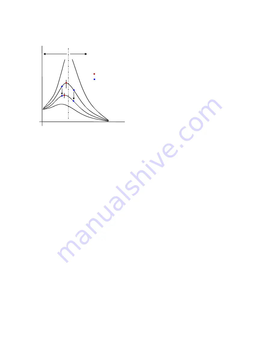
Diagram 4 shows various resonance curves for a feeder with different damping levels. This demonstrates the
relationship between damping and the shift in resonant frequency.
a
=
without damping (theoretical).
b – d =
increasing damping levels.
f
a
=
drive frequency.
f
res
=
resonant frequency
f
res
> f
a
=
under critical operation
f
res
< f
a
=
over critical operation
Diagram 4
One can see from the curves that the resonant frequency of the vibrating system reduces with increased
damping. Different feeder drive characteristics can be achieved by tuning the vibratory system to a value
above or below the drive frequency. In practice both possibilities can be applied.
2.3.2 Under-critical operation
For under-critical operation the drive frequency f
a
is lower than the resonant frequency f
res
. When the damp-
ing increases, by loading the feeder, the resonant frequency gets closer to the drive frequency. In this way
the system compensates itself and is unaffected by load changes. The power and the deflection run in phase
in this drive method, i.e. the air gap at maximum current is smaller than at rest. This method of tuning is cho-
sen mainly for large feed conveyors or products that are inclined to interlock. At very low frequencies the coil
yoke can lock-up when the current comes into phase with the vibratory movement., defined by the under fre-
quency limit.
2.3.3 Over-critical operation
For over-critical operation the drive frequency f
a
is greater than the resonant frequency f
res.
When the damp-
ing increases the amplitude increases. Likewise, interlocking products tend to cause a reduction of the
feeders resonant frequency. In this operating method the power and vibratory movement are phase op-
posed, which dictate the use of a large reaction base and a higher current draw. In practice this method of
tuning is used in automation engineering where a large reaction base can be used, in most instances for
good engineering reasons, and the resonance curve is very flat because of high damping. The forced
stability achieved by high damping must, however, be traded against a high power usage.
3.0 Operating methods for vibratory feeders
3.1 Unregulated drive control
For unregulated control (output voltage control) the feeder
must
be tuned to operate away from resonant
frequency, by a specific amount. This difference determines the stability of a feeder, when it is subjected to
load changes, caused by the product. Depending on the feed system, the difference between the tuned fre-
quency and the resonant frequency is approximately ± 3Hz. When controllers with a fixed frequency are
used (e.g. thyristor or triac), the correct frequency is set by changing the spring pack and/or fitting compen-
sation weights. By using controllers that have a variable frequency output (frequency inverters), the electrical
drive frequency can be easily set to match the mechanical frequency, thus removing the need for time con-
suming mechanical tuning.
4
f
res
> f
a
f
res
< f
a
f
res
f
a
S
[m
m]
f [Hz]
a
b
c
d


