


2.2 The feed wave form
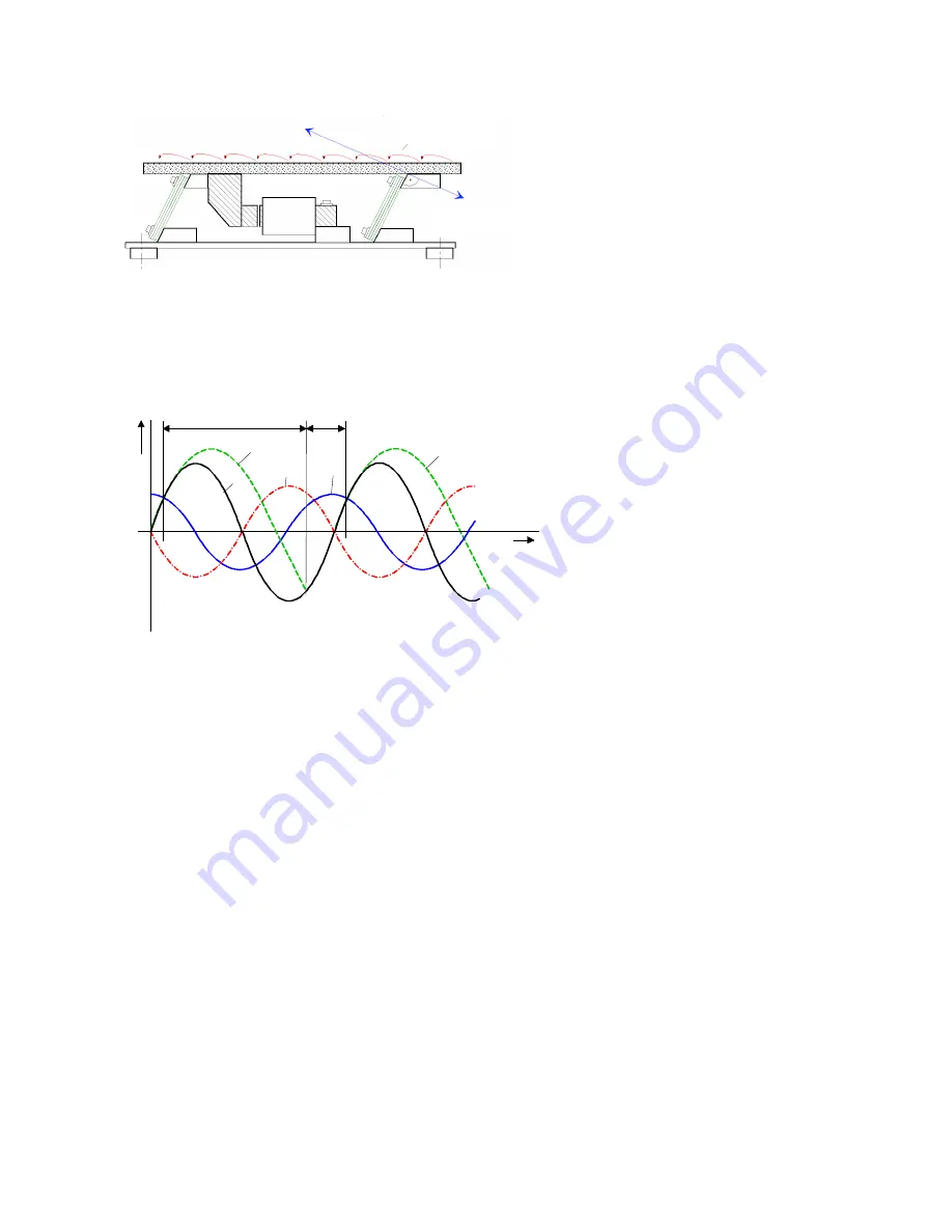
Diagram 2 shows a vibratory drive unit with a unidirectional deflection (linear feeder). The direction of move-
ment is determined by the vibrating angle. The material on the track is accelerated along the deflection path.
Diagram 2
The product describes a trajectory on the track (micro throw principle) which is determined by the vertical
component of the vibration acceleration exceeding that of the basic acceleration. The product lifts off the
feed track during forward movement, follows the trajectory over the time period t
F
(see diagram 3), meets the
feed track again, where it remains for a time period t
B
, in contact with the feed track until the cycle starts
again. The trajectory is so small and fast that it cannot be discerned with the naked eye.
t
F
Trajectory time
t
B
Contact time
sf
Product movement
s
Deflection
a
Acceleration
v
Speed
Diagram 3 Trajectory path of the product
In practice, the feeder throughput is of particular interest. This is dependent on the horizontal component of
the vibrating speed of the feeder during the contact time t
B
and because the take-off point does not coincide
with the highest horizontal speed, the product speed never reaches that of the vibrating speed. The achiev-
able feeder throughput is different for each product and depends on the vibrating frequency and amplitude.
An increase of the feeder throughput cannot be achieved by adjustment amplitude alone; the correct vibrat-
ing frequency must also be selected for the product.
2.3 Vibrating frequency and resonance
Every vibratory system has a resonant frequency, which relates to its mass, spring constant and product
weight. If a feeder could be driven at resonance, in theory the amplitude is infinite and the system would be
uncontrollable. In practice such a condition cannot be achieved without something extra. Mechanical reso-
nance, however, displays a very specific characteristic and so the vibrating frequency of a feeder cannot be
too far away from resonance, otherwise the achieved deflection would be negligible. Furthermore, a damped
system, working at resonance, is not viable because every change of the damping caused by the product
would result in a change of the amplitude and hence the feeders throughput.
Conversely, operating at resonance also offers some advantages. The energy usage is greatly reduced and
the vibration movement becomes much more harmonic (sinusoidal), which results in a much quieter opera-
tion. Modern drive controllers such as the
REOVIB MFS
range constantly monitor the vibration movement
and provide a regulated operation, whereby the vibrating frequency is maintained at resonance and ampli-
tude is held constant.
3
S
sf
a
v
t
F
t
B
S,
a
,v
,s
f
t
sf
T
rajectory
Vibrating angle
α


