


9.0.1 Set up menu for regulation control
E.g. REOVIB MFS 068
Example menu only: for other control units the parameters may be different!
The controller, together with the sensor fitted on the feeder produce a feedback loop, whereby the signal
generated from the sensor determines the control range of the set-point, i.e. the regulator controls the feeder
so that the effective value (feeder power or intensity of vibration) relates to the provided set-point value. Be-
cause the effective value is dependent on the feeder (frequency, acceleration and amplitude) and in addition
depends on the mounting position of the sensor, the regulator must be adapted to suit the output control
range.
This is achieved by using the parameter “P” in menu “C 008”. The measured sensor signal range is adjusted
by changing this value. In most instances a value of less than 100 must be entered, so that the set-point can
reach 100% or can go as high as possible.
When it is not possible to achieve an acceptable range the accelerometer should be mounted in the location
which gives the greatest movement (see the bowl feeder example).
The importance of scaling this value is demonstrated when, for example, a feeder takes a very long time to
ramp up, after it has been switched on.
9.1 Relationship between acceleration and amplitude
The sensor measures the momentary acceleration of the feeder. It generates a sinusoidal output voltage
signal. The acceleration gets higher as the frequency increases. The sensor signal is greater for a higher
frequency and lower amplitude than for a low frequency with higher amplitude.
Acceleration
In practice the acceleration is influenced by gravitational
force and the applied amplitude is measured in mm and so
this gives the following formula:
[ ]
[ ]
[ ]
[ ]
[ ]
497
10
2
81
,
9
2
2
2
3
2
2
2
2
mm
s
Hz
f
mm
s
Hz
f
g
a
n
n
=
⋅
=
π
a[g] = Acceleration ( with respect to gravitational accelera-
tion of 9.81 m/s2)
S
n
[mm] = Applied amplitude
In practice where 497 is approximated to
500 this gives, for example:
1.
Vibrating frequency 50Hz, amplitude 3mm
or
2.
Vibrating frequency 33Hz,Amplitude 5mm
16
f
π
ω
2
=
s
a
2
ω
=
g
a
15
500
3
50
2
=
≈
⋅
=
where
g
a
89
,
10
500
5
33
2
=
≈
⋅
=
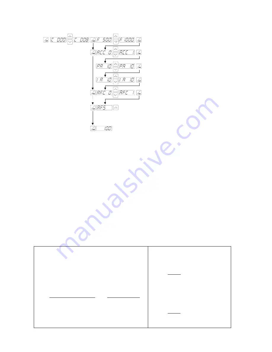
P
P
P
P
P
P
P
Code
008
Regulation P characteristic
(Circuit gain
)
Start freq. search
Automatic frequency control
A.F.C. = 0 =
Off
A.F.C. = I = On
Regulation I characteristic
(
damps oscillations of the feeder
)
Return to normal running mode
P
P
Select regulation mode
ACC. = 0 = Control without sensor
ACC. = I = Regulation with sensor
Vib. frequency
[Hz]
P
P


