REO REOVIB series Скачать руководство пользователя страница 17

 
For  100Hz  (120Hz)  vibrating  frequency,  this  switch  must  be  closed  or  a  link  fitted  and  for  50Hz  (60Hz)  vi-
brating frequency the switch must be open, or a link is removed. 
In the case of 

frequency inverters

 the vibrating frequency has a step less setting through the operator front 

panel.  
 

Coils can be damaged if the vibrating frequency is set incorrectly (too low). 

 
The rating label on a coil is often not very explicit, e.g. 50Hz is stated but no reference is made to whether 
this  is  mains  frequency  or  the  vibrating  frequency  of  the  feeder  (generally  it  refers  to  the  electrical  fre-
quency). It is important (in the case of thyristor and triac controllers) to know if the coil operates with one or 
both of the mains half-waves (6000 or 3000vibs/min). 
 

Coils for 50Hz (3000 vibs/min) are often designated with the additional wording “for rectifier opera-
tion”. 

 
A coil for 6000 vibs/min installed to operate on half-wave (3000 vibs/min) will draw too high a current and will 
inevitably overheat, leading to breakdown. The frequency adjustment range, on frequency controllers, is very 
wide and so it is particularly important to monitor the coil current. 

When in doubt the current must be checked


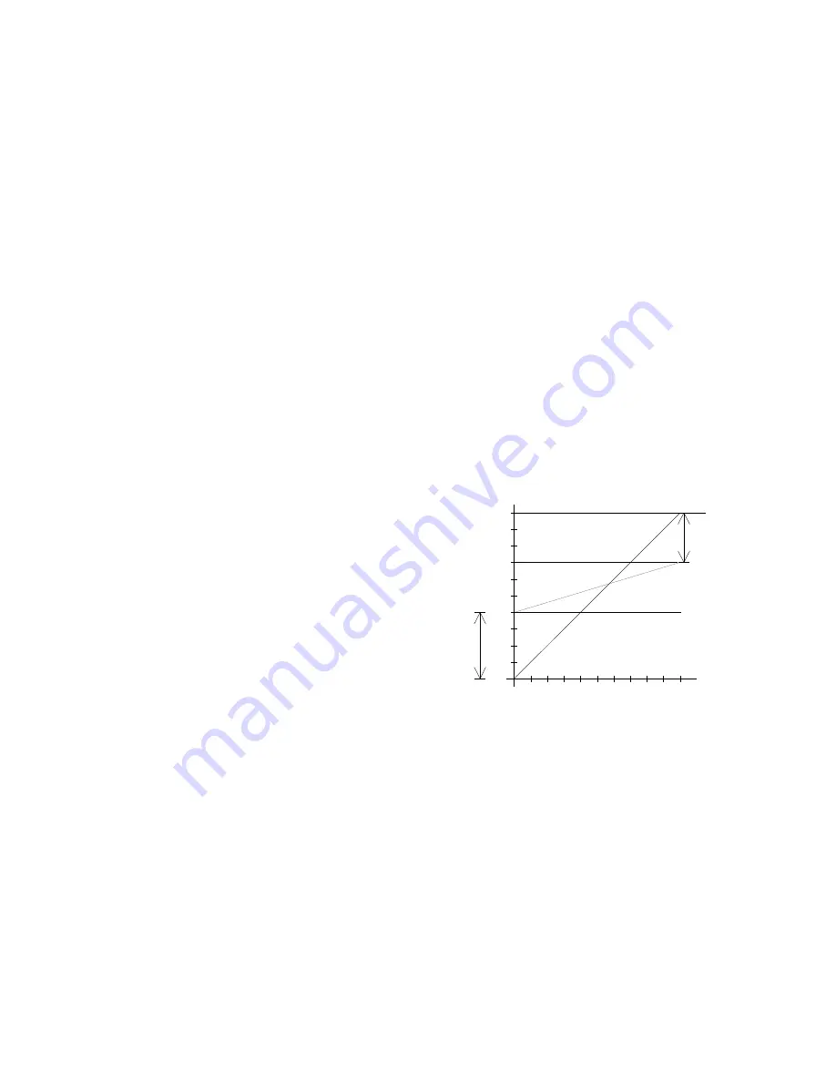
8.2 Setting the feeder throughput 

 
Different  feeder  constructions  (size,  weight,  damping  etc.)  means  that  the  set-point  control  range,  i.e.  they 
has to be trimmed for each individual feeder. In other words, the output voltage value at which material just 
moves  and  also  which  gives  maximum  deflection,  differs  from  feeder  to  feeder.  The  trimmers  Umin  and 
Umax are used for setting the control range, so that it can be fully used, whether this be for control from a set 
point potentiometer, 0...10V control voltage or 0(4)...20mA current signal. 
 
 
Controllers  with  digital  control  panels,  because  of  their 
improved setting abilities, do not require this facility. It is only 
necessary to limit the maximum feeder throughput, to either 
protect the coil against hammering or to limit a feeder that is 
too quick (jamming or interlocking parts). 
 
When  an  external,  analogue,  set-point  signal  is  used  in 
conjunction  with  a  digital  controller,  it  is  still  necessary  to 
adjust the minimum value. 
In this case the setting is as follows: 
 
1.  Increase  the  throughput  setting  to  the  level  where  the 

feeder does not quite feed. 

2.  Now  go  into  the  user  menu  and  select  the  external  set 

point source. The value set previously will remain as the 
minimum level when the throughput signal is “0”.  


9.0 Setting up regulation control of frequency controllers 


  To use regulation mode it is necessary to fit an accelerometer to the vibratory feeder. 


  When  an  accelerometer  is  used  in  regulation  mode,  it  will  sense  and  feed  back 

all

  vibration  signals. 

Stray  signals  can  be  generated  by  neighbouring  equipment,  inadequate  supporting  structures  for  the 
feed equipment or from inadequate mounting of the sensor itself. These can cause incorrect regulation. 
It  is  especially  important  to  ensure  that  there  are  no  external  influences  on  the  feeder,  when  an 
automatic frequency search is being carried out. 


Resonant frequency: 

Depending on the construction of the feeder and mass distribution, it is possible 

to have several frequencies that will exhibit resonance. The additional resonance points are multiples of 
the main resonant frequency. In certain, critical, circumstances the automatic frequency search may not 
locate resonance for this reason and in such cases the frequency must be set manually. 


15 

0

10 20 30 40 50 60 70 80 90 100 [%]

10

20

30

40

50

60

70

80

90

100

[%]

O

utp

ut 

 v

ol

ta

ge

Set point

Um

in

Um

a

x

F

ul

l  

sc

al

e

Содержание REOVIB series

Страница 1: ...REOVIB Control units for flexible automation Hand book for installing and setting up REOVIB controllers Concepts questions and background information ...

Страница 2: ...Reset set point to zero 12 7 2 3 Six key control panel 12 8 0 General manufactures instructions for the installation of REOVIB control units 13 8 1 Before installation 14 8 1 0 Connection diagram for frequency drives 14 8 1 1 Setting the mechanical vibrating frequency 14 8 2 Setting the feeder throughput 15 9 0 Setting up regulation control of frequency 15 9 0 1 Setup menu for regulation control 1...

Страница 3: ...espondingly gives 3600 and 7200 vibrations min REOVIB control units are equally suitable for operating with either frequency and can be set by using a link switch to match the feeder frequency REOVIB Frequency inverter specially developed for use with vibratory feeders provides a highly stable drive frequency independent of the supply frequency tuned to that of the feeder and adjustable in 0 1Hz s...

Страница 4: ...d to as Linear Feeders Vibratory feeders with a spiral track and a spring coil combination that gives a com posite motion that are used for sorting orientating and feeding parts are known as Bowl Feeders 2 1 The vibration wave form The vibratory motion in the case of a vibratory feeder moves backwards and forwards in a straight line The direction of movement is at a specific angle relative to hori...

Страница 5: ...erent for each product and depends on the vibrating frequency and amplitude An increase of the feeder throughput cannot be achieved by adjustment amplitude alone the correct vibrat ing frequency must also be selected for the product 2 3 Vibrating frequency and resonance Every vibratory system has a resonant frequency which relates to its mass spring constant and product weight If a feeder could be...

Страница 6: ...ation For over critical operation the drive frequency fa is greater than the resonant frequency fres When the damp ing increases the amplitude increases Likewise interlocking products tend to cause a reduction of the feeders resonant frequency In this operating method the power and vibratory movement are phase op posed which dictate the use of a large reaction base and a higher current draw In pra...

Страница 7: ...bration amplitude by varying the output volt age The feeder is always running with the greatest effectiveness when operating in this manner For more information refer to section 9 0 Guidance on using regulation control with frequency inverters 4 0 REOVIB Symbols The following icons are used to denote unit functions Straight line vibratory feeder Vibratory feeder with a spiral track Motor driven pr...

Страница 8: ...ly When a half wave only is used this provides a frequency the same as that of the mains supply A frequency inverter can provide a frequency that is independent of the mains supply frequency Vibrating speed Refers to the derivative of deflection against time Amplitude Deflection Deflection of the feeder mm relative to the static air gap between the coil and armature normally expressed as the entir...

Страница 9: ...omponents drops below set a certain level the pre feeder switches on and tops up the feed system Coarse fine control Operation with two feeder speeds fast and slow Pulsed operation Feeder runs with a pulsing on off action e g to separate components Accelerometer or am plitude sensor A sensor to control the actual amplitude of a vibratory feeder Can be used either for monitoring or as a feedback tr...

Страница 10: ...To reduce overfilling when feeding material to a weighing machine e g packing machines a feeder can be fun slower shortly before reaching the target weight Additional contacts are provided in a weigher for this purpose These contacts switch the controller to a second set point level which reduces the feeder through put Upon reaching the target weight the feeder switches off completely This operati...

Страница 11: ...es and falls around the position of the sensor on the feed track The power output from the controller is switched on after product falls below the sensor position and the switch on time delay has expired t2 When product builds up behind the sensor position t4 and the switch off time delay has expired t5 the power output from the control unit switches off The time delays are reset if gaps in the pr...

Страница 12: ...f time delays are set by using trimmers or a programming menu in display panel 6 8 3 Sensor Time out Additional function available in digital controllers when the sensor switches t1 an additional timer Sensor Time out is started After a preset time e g 30 240 sec the feeder is switched off t3 providing that in the meantime no further product has been detected by the sensor The status signal is ini...

Страница 13: ...Code C143 Parameter US PA Below is an explanation of the main setting components that are provided on controllers 7 2 1 Three key control panel The operation and setting up of the unit is achieved by using three keys in conjunction with an LED display that can be found on the front panel These controls are all that is needed for selecting all operating modes and setting all parameters To prevent a...

Страница 14: ... 7 2 3 Six key control panel The six buttons and a LED display found in the front panel are used for operating and setting up the unit All operating methods and adjustable parameters can be set up through this panel The I and O buttons are used for switching the unit ON and OFF however these do not pro vide mains isolation they simply inhibit the power semiconductors The P F and Cursor Buttons are...

Страница 15: ...of their training experience and position as well as their knowledge of appropriate standards regulations health and safety requirements and working conditions are authorized to be responsible for the safety of the equipment at all times whilst carrying out their normal duties and are therefore aware of and can report possible hazards Definition of qualified employees according to IEC 364 The cont...

Страница 16: ... be a loss of feeder throughput or the coils will overheat The vibrating frequency for thyristor or triac controllers is selected by using a switch normally a link switch depending on the type of controller The programming menu is used in digital controllers 14 F K L1 REOVIB MFS L1 N PE N PE L1 PE A1 A2 Line reactor Recommended for reducing mains distortion PFC and protecting the drive unit under ...

Страница 17: ...ontrol voltage or 0 4 20mA current signal Controllers with digital control panels because of their improved setting abilities do not require this facility It is only necessary to limit the maximum feeder throughput to either protect the coil against hammering or to limit a feeder that is too quick jamming or interlocking parts When an external analogue set point signal is used in conjunction with ...

Страница 18: ... this value is demonstrated when for example a feeder takes a very long time to ramp up after it has been switched on 9 1 Relationship between acceleration and amplitude The sensor measures the momentary acceleration of the feeder It generates a sinusoidal output voltage signal The acceleration gets higher as the frequency increases The sensor signal is greater for a higher frequency and lower amp...

Страница 19: ...ch menu C 008 select Parameter A F S and press a cursor key to start search this will determine the optimum feeder setting When the resonant frequency has been found the controller will complete the search routine and return to the previous throughput setting 0 9 4 Optimizing regulation 9 4 1 Control range adjustment Set Parameter P in menu C 096 to 50 maximum limit Increase the through put A from...

Страница 20: ...t depend on a true sine wave for mains voltage or current should be used a sine wave is only generated at full output with full wave control The output from frequency controllers is generated by an electronic inverter with pulse width modulated switching The voltage and current values cannot be measured with normal instruments Preferably a moving iron measuring instrument analogue meter should be ...

Страница 21: ...use in the controller and replace if necessary Control input Inhibit Enable correctly set Feed equipment has no power Check that the correct vibrating frequency has been selected and change if necessary Check supply frequency 50 60 Hz Vibrating frequency and supply frequency must correspond Setting of trimmer Umax is too low adjust Umax Feed equipment vibrates aggressively coil hammers Incorrect v...

Страница 22: ...played and feeder does not work no enable signal provide enable signal using con tacts or 24VDC signal fit a link between enable termi nals invert parameter En After running for a short time the feeder stops and Error SE flashes in the dis play sensor time out has been activated no mate rial available no track sensor fitted defective track sensor cancel sensor time out parameter EE check sensor ch...

Страница 23: ...check mains voltage control unit may have to be changed for another type contact manufacturer ERROR ACC Sensor fault defective sensor wrong sensor wiring test sensor check wiring ERROR ETP External tempera ture switch external temperature switch has reached his maximum no temperature switch con nected check magnet temperature bypass the magnet tempera ture input ERROR SE Track control sensor time ...

Страница 24: ...o 28 bud 20 PL 04 703 Warszawa Tel 48 0 22 812 3066 Fax 48 0 22 815 6906 E Mail croma croma com pl Internet www croma com pl Spain REO ESPAÑA 2002 S A C Manuel Ventura i Campeny 21B local 9 E 08339 Vilassar de Dalt Barcelona Tel 34 937 509 994 Fax 34 937 509 995 E Mail info reospain com Internet www reospain com Switzerland REO ELEKTRONIK AG Im Halbiacker 5a CH 8352 Elsau Tel 41 0 52 363 2820 Fax ...

Отзывы: