


11
1.800.627.4499
Integral Indirect Gas-Fired Heat Module
OPTION
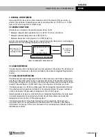
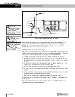
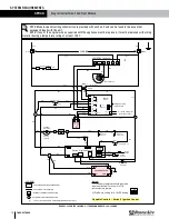
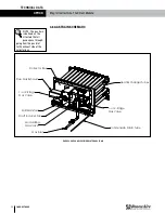
FIGURE 2.1.0 INDOOR VERTICAL VENTING FOR FLUE EXHAUST
-
-
-
RenewAire LLC
SCALE:1:30
SIZE
DWG. NO.
A
-
-
BY
DATE
--
Vent FEB19
10/29/18
AND TOL. ANSI Y14.5
CAH
SURFACE FINISH =
FINISH:
DESCRIPTION OF REVISION
TITLE:
LEVEL
DN-3-IN GH SEPARATED VERTICAL VENT
TOLL FREE: (800) 627-4499
--
DATE:
CHECKED BY:
3
REMOVE ALL BURRS, BREAK
63 MICROINCH MINIMUM
MATERIAL:
DATE:
SEE BILL OF MATERIAL
SHARP EDGES.
DO NOT SCALE DRAWING.
DRAWN BY:
SHEET 1 OF 1
DN IN GH Separated Vert
APPLICABLE STANDARDS: DIM.
UNLESS OTHERWISE SPECIFIED,
DIMENSIONS ARE IN INCHES.
TOLERANCES:
LINEAR 0.015
HOLE SIZE 0.005
ANGULARITY
4510 Helgesen Dr.
Madison, WI 53718 USA
TEL: (608) 221-4499
FAX: (608) 221-2824
SEE BILL OF MATERIAL
Roof Deck
Vent Terminal(s)
Listed Vertical
(Both Pipes)
Exhaust Vent
Cleanout Cap
Tee Fitting with
Drip Leg and
Combustion Air
Inlet
Min.
Min.
(0.75m)
expected snow depth.
Adjoining Building
Note: Provide sufficient
2.5 ft
clearance (height) to exceed
18 in.
(0.46m)
6 ft.
(1.8m)
Min.
To Wall or
18 in.
(0.3m)
Min.
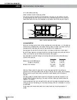
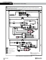
2.1.2.2 Horizontally Vented Heat Modules
Pressures in Category III venting systems are positive and therefore care must be taken to avoid
flue products from entering the heated space. Use only vent materials and components that are
UL listed and approved for Category III venting systems.
All vent pipe joints must be sealed to prevent leakage into the heated space. Follow instruction
provided with approved venting materials used. The proper vent pipe diameter must be used, to
insure proper venting of combustion products.
The total equivalent length of vent pipe must not exceed 50 feet [15.25 m]. Equivalent length is
the total length of straight sections, plus 5 feet [1.52 m] for each 90˚ elbow and 2.5 feet [0.76
m] for each 45˚ elbow.
The vent system must also be installed to prevent collection of condensate. Pitch horizontal pipe
runs downward ¼ inch per foot [21mm/meter] toward the outlet to permit condensate drainage.
Insulate vent pipe exposed to cold air or routed through unheated areas. Insulate vent pipe runs
longer than 10 feet (3m). Insulation should be a minimum of ½ inch [12mm] thick foil faced
material suitable for temperatures up to 500˚F [260˚C]. Maintain 6 inch [152 mm] clearance
between vent pipe and combustible materials.
A vent cap listed for horizontal venting must be provided. Vent cap inlet diameter must be same
as the required vent pipe diameter. The vent terminal must be at least 12 inches [305 mm]
from the exterior wall that it passes through to prevent degradation of building material by flue
gases. The vent terminal must be located at least 1 foot [305 mm] above grade, or in snow
areas, at least 3 feet [1 m] above snow line to prevent blockage. Additionally, the vent terminal
must be installed with a minimum horizontal clearance of 4 feet [1.2 m] from electric meters,
gas meters, regulators or relief equipment.
NOTE: For
assistance with vent
sizing and design,
contact a reputable
company such as Precision
Vent or Tjernlund.
NOTE: All
installations must
comply with
SMACNA guidelines.
NOTE: All ductwork
and venting as
shown in illustra-
tions is supplied by others
and field-installed.
NOTE: A field-sup-
plied and installed
power vent may
be required for vent runs
longer than 50 equivalent
feet [15.25 m].
SYSTEM REQUIREMENTS


