background image

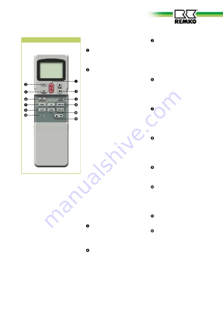
  "ECONOMIC RUNNING" button


Pressing this button will auto-
matically increase or decrease 
the target temperature by 1 
°C within an hour in cooling 
and heating mode respective-
ly.


"AIR DIRECTION" Button


With this button, the desired 
fin position can be set. There 
are 5 positions and an oscillat-
ing function available.

  "SWING" Button


This button directly activates 
the oscillating function of the 
fins for better air distribution 
in the room.

  "TIMER ON/OFF" button

  This button serves to program 

the automatic activation time 
for the device within the next 
24 hours. 


  "CLOCK" button

  This button opens the time 

program.


"OK" button

  This button transfers the pro-

grammed data to the indoor 
unit.

  "CANCEL" button
 

This button stops the set timer 
program.


"LOCK / RESET" button 


(flush buttons

  The left LOCK button pre-

vents subsequent operation, 
the right RESET button resets 
the display.

Buttons on the remote control

  "ON/OFF" Button

Press this button  
to start the unit.  

  "MODE" button


Press this button 
to select the operating mode. 
The  
indoor unit has 5 modes:

  1. Automatic mode  

In this mode, the unit works in 
cooling or in heating mode. 

  2. Cooling mode 

In this mode, the warm room 
air is cooled to the  
desired temperature. 

  3. Dehumidification mode

In this mode  
the room is mainly dehumidi-
fied, the adjusted temperature is 
retained.

  4. Heating mode 
  In this mode, the warm air in 

the room is warmed up to the 
desired temperature.

  5. Circulation mode 

In this mode, the air in the room 
is recirculated. 
Temperature selection is not 
possible.

  Button "Temp 

▲ ▼ "


This button is used to 
select the desired temperature 
between 17 - 30°C.

  "FAN SPEED" button


Press this button to set the 
required fan speed. 4 settings 
are available: automatic, high, 
medium and low fan speed.

Buttons on the remote control

7

Содержание RVD 351DC

Страница 1: ...Issue D V03 REMKO RVD RVD 351DC RVD 521DC Inverter ceiling mounted air conditioner in split design Operation Technology Spare parts...

Страница 2: ......

Страница 3: ...tion and recycling 4 warranty 4 Transport and packaging 5 Description of the equipment 5 Operation 6 12 Shutdown 13 Care and maintenance 13 14 Troubleshooting and customer service 15 16 Installation i...

Страница 4: ...stalled by qualified per sonnel The setup connection and operation of the unit and its components must be in accord ance with the operating condi tions stipulated in this manual and comply with all ap...

Страница 5: ...ant circuit with compressor fin liquefier liquefier fan reverse flow valve and flow regulator The outdoor unit is controlled via the regulation of the indoor unit The indoor unit is designed for indoo...

Страница 6: ...e manually operated Problems are shown in code see chapter Troubleshooting and Customer service CAUTION Immediately replace flat batter ies with a new set otherwise there is a risk of leakage It is re...

Страница 7: ...t LOCK button pre vents subsequent operation the right RESET button resets the display Buttons on the remote control ON OFF Button Press this button to start the unit MODE button Press this button to...

Страница 8: ...modes The nominal temperature can be preselected and is then applied in automatic mode The fan speed is automatically adapted to the given circumstances AUTOMATIC MODE COOLING or HEATING The nominal...

Страница 9: ...rns the cooling on again after a waiting period of 3 minutes COOLING mode COOLING OPERATION and In dehumidification mode the room temperature is set to 24 C Due to the low temperature of the refrigera...

Страница 10: ...n the room The inverter controller checks the difference between the adjusted target temperature and the actual room temperature In the event of a greater difference a higher cooling performance is cr...

Страница 11: ...function of the air discharge fins can be adjusted with this button The air distribution in the room is improved with the swing function In order to adjust the aim of the air discharge fins to a parti...

Страница 12: ...F TIMER ON button activation delay Activation delay TIMER OFF button switch off delay CANCEL delete timer program Switch off delay Time stored TIMER ON TIMER ADJUST TIMER ADJUST TIMER ADJUST OK TIMER...

Страница 13: ...ice life of the unit Care Ensure the indoor unit and out door component are protected against dirt mould and other deposits Clean the equipment using a damp cloth Do not use any caustic abrasive or so...

Страница 14: ...2 Turn the dirty side until it faces up 5 Any dirt can be cleaned off us ing lukewarm water and mild cleaning agents To do so turn the dirty side downward Fig 3 6 When using water allow the filter dr...

Страница 15: ...ot transmitted when in terference sources are operational Button in remote control jammed two buttons pressed at same time Does the Send symbol appear on the display Release the button only press one...

Страница 16: ...that the compres sor oil can flow back without obstruction LED Operation LED Timer LED Defrost LED Alarm Display outdoor unit Cause Required action E0 EEPROM error Check EEPROM E2 Communication error...

Страница 17: ...densation line Injection pipe Suction pipe PVC tube Selection of the installation location Interior unit The indoor unit is designed for horizontal wall installation above doors However it can also be...

Страница 18: ...ir work and facilitate optimum air distribution 500 1000 1000 1000 1000 E C B A D Air intake Air outlet All values in mm Minimum clearances Ensure a continuous and unob structed air flow from outside...

Страница 19: ...on nections to a second room or a fresh air intake are required See section Connections to Installation should only be performed by authorised spe cialists NOTE a second room or a fresh air intake 3 F...

Страница 20: ...ns NOTE Flanging tool 7 Flanging the refrigerant pipe Refrigerant pipe Deburrer 6 Deburring the refrigerant pipe 8 Correct flange shape Tighten 1 spanner Counter 2 spanner 9 Tighten the fitting Tighte...

Страница 21: ...e required to generate the vacuum is dependent on the pipe work volume of the indoor unit and the length of the refrigerant pipes This always takes at least 60 minutes Once any foreign gases and humid...

Страница 22: ...ram 4 Re assemble the unit Terminal block Control line Cover Control line from the out door unit 12 Connecting the indoor unit Connecting the outdoor com ponent Proceed as follows to connect the cable...

Страница 23: ...caps are tight after carrying out any work on the refrigerant circuit If necessary use appropri ate sealant products NOTE Functional test for cooling and heating modes 1 Remove the caps from the valv...

Страница 24: ...e 10 35 40 11 40 45 C 12 45 50 13 50 55 C 14 55 60 15 60 65 C 16 65 70 Display Temperature 15 7 5 20 5 0 C 25 2 5 30 0 C 35 2 5 40 5 0 C 45 7 5 50 10 0 C 55 12 5 60 15 0 C 65 17 5 C 70 20 0 C 75 22 5...

Страница 25: ...Steuerleiter DM Display Y G c Blau Y G CN5 GM P1 Lila Wei Netzzuleitung Innenteil Rot Wei CN4 CN11 CN5 CN7 CN9 Wei C5 Wei Schwarz Rot CN3 CN2 T1 T2 T2 T1 CN14 CN10 CN15 E Y X Schwarz Grau Gelb Schwarz...

Страница 26: ...5 CN6 CN4 CN8 CN10 CN9 Blau Ventilator CN1 CN2 L N L N P 1 L H Sensor Hei gas Sensor Au entemperatur Sensor Austritt Verfl ssiger Elektronisches Expansionsventil Leistungsplatine zum Innenger t Steuer...

Страница 27: ...dimensions and constructional design as part of the ongoing technical development process All values in mm 650 650 400 610 28 580 A D E B C RVD 351 521 DC IT RVD 351 521 DC AT RVD 351 DC RVD 521 DC A...

Страница 28: ...1110955 1110956 7 Vaporiser 1110957 1110958 8 Condensation pump cpl 1110959 1110959 9 Fan wheel 1110960 1110961 10 Vaporiser fan motor 1110962 1110963 11 Control PCB 1110964 1110965 12 Transformer 11...

Страница 29: ...alve injection pipe 1111006 1111007 10 Reverse flow valve 1111008 1111009 11 Control PCB 1111010 1111011 12 Condenser compressor 1111012 1111013 Spare parts not illustrated E Box complete 1111014 1111...

Страница 30: ...T RVD 521DC IT Adjustment range room temperature C 17 30 Operating range C 17 31 Air flow volume per speed setting m h 510 530 680 560 710 800 Sound pressure level per speed setting 3 dB A 33 37 40 37...

Страница 31: ...Notes 31...

Страница 32: ...ore than mere salespeople they must primarily act as advisers in air conditioning and heating technology for our customers Customer Service Our units work precisely and dependably Should a failure occ...

Отзывы: