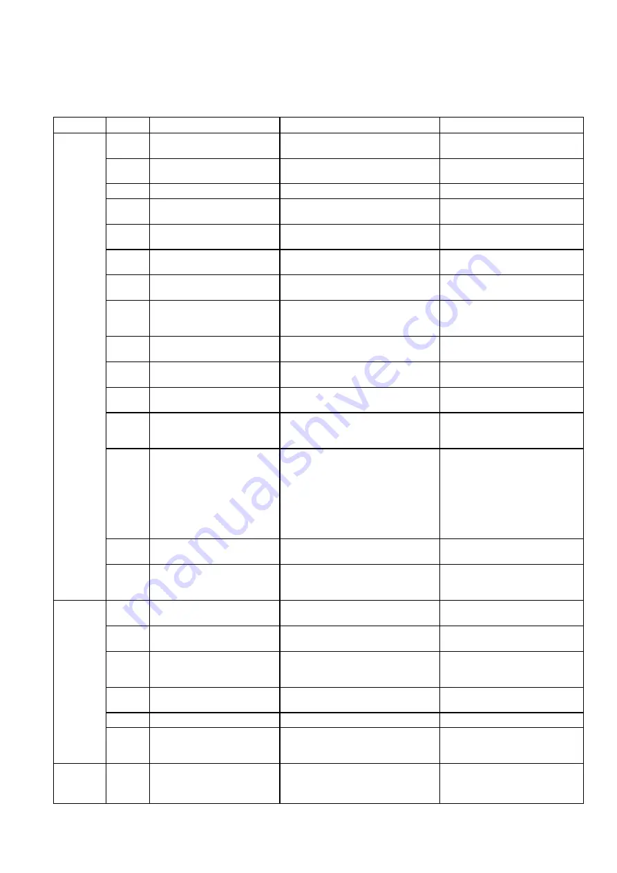
background image

11 

Troubleshooting 


This unit has been designed based on state-of-the-art manufacturing methods and it has been tested repeatedly to 
ensure that it is working properly. However, should problems occur, refer to the following list. 

Problem 

Alarm 

Possible cause 

Check 

Remedy 

The unit 
does not 
start or it 
switches 
itself off 
automati-
cally. 


Power failure


Are all other electrical components 
working? 

Check voltage and wait for the 
unit to start again.


Power fuse / power supply de-
fective


Are all other electrical components 
working?


Maintenance by authorised  
personnel


Waiting period too short 

Is the COMP LED blinking? 

Schedule longer waiting periods 


Regulation is not working 

Is the LINE LED and to the  
COOL LED lit up? 

Connect current and select the 
COOL operating mode 


Incorrect discharge tempera-
ture or parameter setting 

Check setting 

Change setting 

E01/E02 
E21/E22 

High-low pressure alarm 

Are the fans rotating? 
Is the pressure in the cold cycle OK? 

Have checked by authorised 
company 

E00/E21 

Remote control / Connection 
to C2-DIN defective 

Is the display working?  
Is the connection OK? 

Replace remote control or re-
establish connection between 
CH-DIN and C2-DIN 

E03/E23  Compressor overheating 

Is the temperature of the compressor 
above approx. 100 °C? 

Maintain operating ranges, clean 
fins 

E04/E24 

Liquefaction temperature too 
high 

Are the fins clean and have the oper-
ating ranges been maintained? 

Clean fins, place unit in the 
shade  

E05/E25  Frost protection activated 

Is the supply temperature 4°C or 
lower? 

Increase discharge temperature 

E06/E07/
E26/E27/
E40 

Sensors defective ST1 to ST6 

It is the alarm activated when the 
sensor is replaced? 

Replace defective sensors 

E41 

Flow switch (differential pres-
sure monitor) activated 

Are the following values OK: 

Volume of current (too large/small) 

No air in the monitoring pipes 

Circulation pump 

Does the monitor switch on and off 

Stop mechanisms are open 

Water pressure too high/low 

Have checked by authorised 
company 

E42 

Hardware defective 

Does the regulation function 
smoothly? 

Have regulation replaced by 
authorised company 


Compressor contact defective 

Is the COMP LED lit up and is there 
current on the contact? 

Have the contact or compressor 
replaced by an authorised com-
pany 

The unit is 
either not 
cooling at 
all or only 
a little bit 


Heating capacity was in-
creased 

Has there been a structural change?  Maintain safety zones 


Supply temperature too high 

Is the supply temperature approx. 
5 ... 10 °C? 

Reduce discharge temperature 


Air in the system 

Have automatic ventilators been 
mounted on the highest possible po-
sition? 

Ventilate manually or integrate 
ventilators 


Liquefaction temperature too 
hot 

Are the fins clean and have the oper-
ating ranges been maintained? 

Clean fins, place unit in the 
shade, maintain operating ranges 


Incorrect parameter settings 

Check settings 

Change settings 


Sporadic operation because 
cooling requirements are too 
low 

Has the system been designed for 
smaller measurements? 

Increase the quantity of water by 
installing a storage module 

Water 
leaks out 
of the unit 


Leaks in pipes or defective in-
sulation 

Are there leaks and have all lines 

been insulated? 

Seal and insulate 


Incorrect electrical rotational 
direction 

Did the phase-sequence relay switch 
through? 

Change the rotational direction 

Содержание RKW 1000 INOX

Страница 1: ...REMKO powerful like a bear REMKO RKW 1000 9800 INOX Stainless Steel Chiller Edition GB M11 Operation Technology Spare Parts...

Страница 2: ......

Страница 3: ...ce Personnel 14 Unit Assembly 14 Storage Modules for RKW 3600 to 9800 I 17 Cable Remote Control 20 Electrical Connection 21 Hydraulic System 24 Initial Operation 25 Environment and Recycling 26 Servic...

Страница 4: ...s by means of a quiet fan When the air in the room leaves the unit it is cooled demoisturized and filtered The water warms up and transports the heat absorbed from the room back to the outer part wher...

Страница 5: ...arge amounts of dust or aggres sive air Installation and repair work may only be performed by authorised personnel Cleaning and minor maintenance work made only be performed by the operator or an auth...

Страница 6: ...on both displays show a value continuous display After the SET button has been pressed the code display parameters starts blinking The displayed values can be increased or de creased using the arrow k...

Страница 7: ...g the corresponding programmed output current to the CTK 1 CTK 2 output of the TK 1 TK 2 fan board The fan motor rotation can be controlled by the modulat ing output current Compressor LED This LED is...

Страница 8: ...in hours Not installed Operating hours of Compressor 2 23 Fan s Cycle 2 01 02 04 06 Not installed Fans in operation Off not in use Time delay ON OFF 25 Rotations condenser fan s Cycle 2 Not installed...

Страница 9: ...i n s t o b l i n k w h e n t h e S E T button is pressed This mode displays the options for changing the parameters to the programmer If one of the arrow keys is now pressed the parameter jumps to t...

Страница 10: ...ycle 2 E40 Sensor defective ST 1 incoming water E41 Flow switch differential pressure monitor activated E42 Hardware defective The second parameter level can be programmed to reset the alarms Enter th...

Страница 11: ...ture E06 E07 E26 E27 E40 Sensors defective ST1 to ST6 It is the alarm activated when the sensor is replaced Replace defective sensors E41 Flow switch differential pres sure monitor activated Are the f...

Страница 12: ...ater chiller inch 1 1 2 2 x 2 Outgoing water chiller inch 1 1 2 2 x 2 Filling connection inch 1 2 Sound pressure level 2 dB A 43 44 49 48 48 53 54 Refrigerant R 407C Cold cycles Compressor type 1 Scro...

Страница 13: ...tgoing water inch 1 inside 1 inside 1 inside 2 inside 2 inside 2 x 2 inside 2 x 2 inside M filling connection water inch outside outside outside Fan number mm 450 2 450 2 630 1 630 2 630 2 800 2 800 2...

Страница 14: ...room will heat up and the chiller will switch off due to a malfunction This occurs once the room temperature exceeds the upper operating range of the set value of the safety mechanism Minimum distance...

Страница 15: ...sorbers in this series These must be connected to statically permissi ble and level building or structural components The locations for attachment described below are for fastening the vibration absor...

Страница 16: ...liers must be used to mount the pipe lines on the RKW so as not to create any strain on the pipe lines in the inside of the unit If the chiller is only initially operated with a single part of the ove...

Страница 17: ...ge module 3 for RKW 8000 and 9800 INOX 2 x 216 l tanks safety component 3 kPa and MAG without pump Ref No 1611545 4 Storage module 4 for RKW 8000 and 9800 INOX 2 x 216 l tanks safety component 3 kPa a...

Страница 18: ...a 5 8 6 10 8 11 10 11 15 13 Available external pressure differential kPa 92 89 59 66 47 32 Electrical connection V 3 400 3 400 3 400 Power Current consumption kW A 0 55 1 44 0 55 1 44 0 75 1 86 1 1 2...

Страница 19: ...ption max 1 44 A 1 44 A 1 86 A 400 V 50 Hz 3 N PE Characteristic curve of the pump RKW 3600 4500 INOX storage module 2 Characteristic curve of the pump RKW 8000 9800 INOX storage module 4 Characterist...

Страница 20: ...contact with drinking water or food antifreeze L is to be given preference because it contains the physiologically harmless substance 1 2 propylene glycol The data provided in the table refers to anti...

Страница 21: ...AT 9 Differential pressure monitor Neutral contact 15 17 AT 7 Heating cooling removed Neutral contact 15 18 closed AT 10 On Off remote control contact for heating pump Neutral contact 19 20 RL 1 Glob...

Страница 22: ...Verfl ssiger fan 1 Potentialfreier Kontakt for regulating cool ing EXTERNAL Flow switch EXTERNAL Phase sequence relay Terminal strip M1 Terminal strip M2 Compressor motor Relay compressor ST 1 Tempera...

Страница 23: ...4 L1 N L1 12V 12V N Pri 230V CH DIN regulation C2 DIN regulation Additional module for the remote control Transformer 220 12 V in the switch box RKW Operating module Maximum line length 50 meter Assem...

Страница 24: ...1 15 13 3 1 2 12 17 14 10 16 18 9 6 5 4 7 8 15 13 3 Hydraulic Diagram RKW 8000 9800 INOX 1 2 12 17 14 1 16 18 9 6 5 4 7 8 1 15 P 10 19 Terminal strip M1 Condenser fan 1 and 2 Klemmleiste M2 Compressor...

Страница 25: ...is correct The electrical lines of the system must be checked that they are attached properly to the terminal strips Prior to operation all screws in the water system must be checked to ensure that th...

Страница 26: ...then select a higher drainage temperature 17 The supply temperature is approx 5 Kelvin under the drainage temperature for the rated flow rate 18 If the supply temperature is below the factory setting...

Страница 27: ......

Страница 28: ...REMKO GmbH Co KG Klima und W rmetechnik D 32791 Lage Im Seelenkamp 12 D 32777 Lage PO Box 1827 Phone 49 5232 606 0 Fax 49 5232 606260...

Отзывы: