England
en
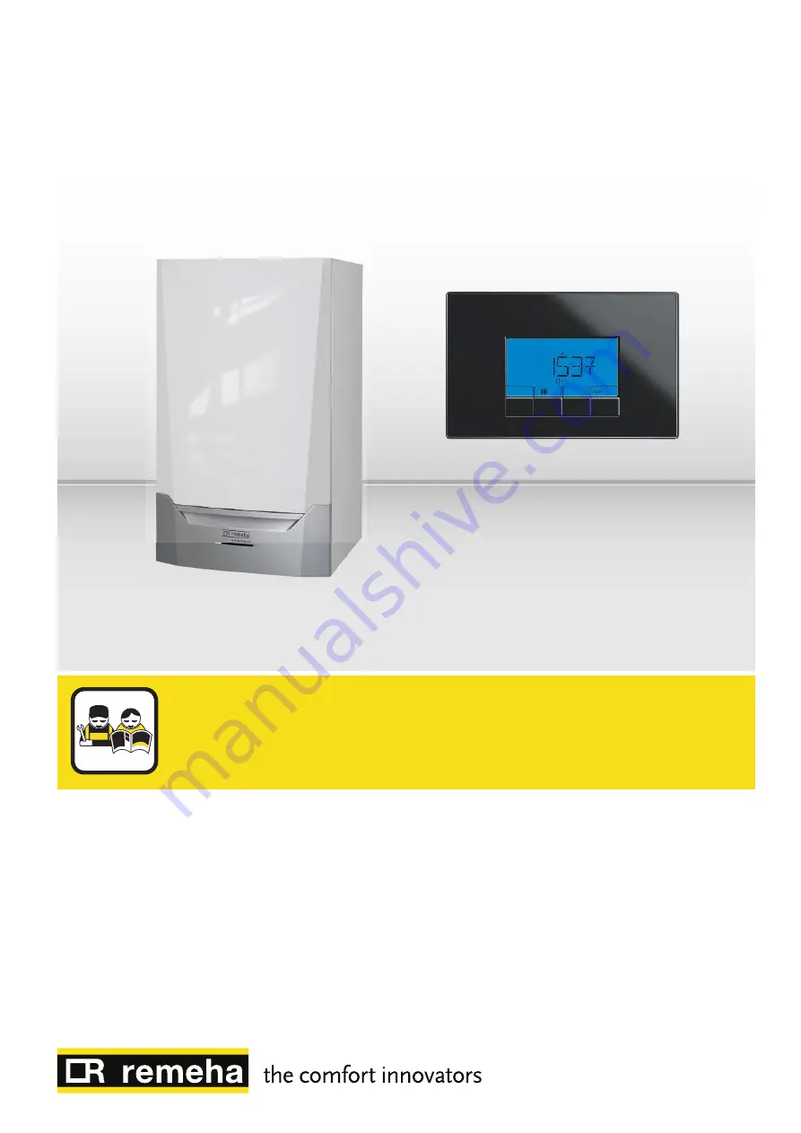
Installation and user manual
Control panel
HMI S-Control
Страница 1: ...England en Installation and user manual Control panel HMI S Control...
Страница 2: ...sing the product and keep it in a safe place for later reference In order to ensure continued safe and efficient operation we recommend that the product is serviced regularly Our service and customer...
Страница 3: ...15 7 2 1 Changing user parameters 15 7 2 2 Changing the central heating flow temperature 15 7 2 3 Changing the DHW temperature 16 7 2 4 Setting the Timer Program 16 7 2 5 Changing installer parameter...
Страница 4: ...r must abide by the following instructions Read and follow the instructions given in the manuals provided with the appliance Install the appliance in compliance with prevailing legislation and stand a...
Страница 5: ...mprove user safety to prevent problems and to guarantee correct operation of the appliance Danger Risk of dangerous situations that may result in serious personal injury Danger of electric shock Risk...
Страница 6: ...1 1 Directives This product complies with the requirements of the following European Di rectives and Standards 2006 95 EC Low Voltage Directive 2004 108 EC Electromagnetic Compatibility Directive 3 Te...
Страница 7: ...for user level parameters can be changed The solar boiler is on and the heat level of the boiler displayed Service menu settings for installer level parameters can be changed Displaying the system wat...
Страница 8: ...ems of information are displayed one after the other Display control panel version Search for connected options Load information from CU board Display of CU board software version Display of CU board...
Страница 9: ...e right 4 Press the key to move the cursor to the left 5 Press the key to confirm selection of the required menu or pa rameter 6 Press the or key to modify the value of the parameter 7 Press the key t...
Страница 10: ...e 1 Navigate to the Counter menu 2 Press the key to open the Operating hours Timer Program Time display menu 3 Keep pressing the key until the Time display menu is displayed 4 Press the key to access...
Страница 11: ...ay and flashes to show the cur rent status of the central heating 3 Press the key to change the current status The symbol appears on the display and flashes to show the changed status 4 Press the key...
Страница 12: ...rameter is part of the timer program change only if necessary 20 Room set point 5 to 30 C 20 CH group control 0 internal timer program 1 manual control 2 according to frost protection 3 temporary 1 Se...
Страница 13: ...0 C 6 Night time set point for CH operation 5 to 30 C 16 Comfort base point for CH operation 15 to 90 C 15 Night time base point for CH operation 5 to 90 C 15 Heating curve gradient 0 to 4 only with o...
Страница 14: ...g 7 Switched in the event of boiler maintenance mes sage 8 Switched if boiler is running for CH 9 Switched if boiler is running for DHW 10 Switched if CV pump is running 11 Switched if boiler is locke...
Страница 15: ...he main display 7 2 2 Changing the central heating flow temperature 1 Press the key once to select the central heating flow tempera ture The set flow temperature appears on the screen 2 Press the key...
Страница 16: ...m Time Display menus can be accessed only if the icon flashes 3 Press the key for the Operating hours menu or press the key for the next menu 4 Press the key for the Timer Program menu or press the ke...
Страница 17: ...Repeat steps 3 to 5 to define the switching times S1 to S6 and the associated status C1 to C6 10 Press the h key to go back to the main display Example Times Monday Tuesday Wednesday Thursday Friday S...
Страница 18: ...key to confirm the new value of the parameter 9 Press the h key twice to go back to the main display 7 2 6 Setting the maximum output for central heating See graph for the relationship between output...
Страница 19: ...tting appears on the screen 9 Press the or key to modify the value Note Transfer the value from the corresponding data plate see data plate 10 Press the key to confirm the selection The factory settin...
Страница 20: ...s next to the flame symbol at the top left of the screen 3 To go back to the main display press the h key once Forced part load or full load is switched off 7 2 10 Activating the manual mode menu 1 Na...
Страница 21: ...te the boiler PCB To do so follow these steps 12 Press the h key and go back to the selection menu The icon flashes 13 Press the or key to navigate again to the icon The current PCB is displayed 14 Pr...
Страница 22: ...ss the h key twice to go back to the main display Tab 6 Current values Value Description Unit DHW active Status Sub status Circulation pump 0 no pump connected Flow temperature C Heat exchanger temper...
Страница 23: ...t mode Tab 8 Sub status numbers Sub status Stand by mode Anti hunting Start external pump Open flue gas damper external gas valve Increase fan speed Pre ventilation Wait for enable signal Burner on Pr...
Страница 24: ...PCB version 3 Press the key to receive information about the optional connec ted PCB for example SCB 01 4 Press the key to receive information about the next connected PCB This information is only di...
Страница 25: ...tion for CH operation kWh 1 Energy consumption for DHW operation kWh 1 Number of circulation pump starts 1 Number of three way valve switchings for DHW 1 Number of three way valve switching hours for...
Страница 26: ...p valves Check the water pressure Check the cleanliness of the heat exchanger Check that the installation has been correctly vented to remove air Sensor error Check that the sensors are operating corr...
Страница 27: ...ction check the connection Waiting time release signal has elapsed External cause remove external cause Wrong parameter set check the parameters Bad connection check the connection Communication error...
Страница 28: ...ncorrectly fitted sensor check that the sensor has been correctly fitted Faulty sensor replace the sensor Flue gas sensor short circuited Bad connection check the wiring and connectors Incorrectly fit...
Страница 29: ...e wiring between the PCU electronic PCB and the ignition transformer Check that the SU electronic PCB is correctly in place Check the ionisation ignition electrode Check breakdown to earth Check the c...
Страница 30: ...r Check that the gas valve is fully opened Check the gas supply pressure Check the operation and setting of the gas valve unit Check that the air supply inlet and flue gas outlet are not blocked Check...
Страница 31: ...e Failure menu is available only if the icon flashes 3 Press the key to access clearing the error memory 4 Press the key to clear all error messages from the error memo ry 5 After a while the main dis...
Страница 32: ...8 Troubleshooting 32 7616014 v 03 15022016...
Страница 33: ...8 Troubleshooting 7616014 v 03 15022016 33...
Страница 34: ...8 Troubleshooting 34 7616014 v 03 15022016...
Страница 35: ...nological information contained in these technical instructions as well as any drawings and technical de scriptions supplied remain our property and shall not be multiplied without our prior consent i...
Страница 36: ...cial UK Innovations House 3 Oaklands Business Centre Oaklands Park RG41 2FD Wokingham Tel 44 0 118 978 3434 Fax 44 0 118 978 6977 Internet www remeha co uk E mail boilers remeha co uk 7616014 v 03 150...