


-
F
rançaIs
-
Manuel d’utilisation
35
SommairE
INTRODUCTION
....................................................................... 36
TRANSPORT, STOCKAGE ET MANUTENTION
....................................... 36
DEBALLAGE/MONTAGE
.............................................................. 37
LEVAGE/MANUTENTION
............................................................. 37
EMPLACEMENT POUR L’INSTALLATION
............................................. 37
BRANCHEMENT ELECTRIQUE ET PNEUMATIQUE
.................................. 38
CONSIGNES DE SECURITE
............................................................ 38
DESCRIPTION DES DEMONTE PNEUS PROMAXX 8150
............................ 39
DONNEES TECHNIQUES
.............................................................. 39
EQUIPEMENT
.......................................................................... 40
ACCESSOIRES EN OPTION
............................................................ 40
CONDITIONS D’UTILISATION PREVUES
............................................. 40
PRINCIPAUX ELEMENTS DE FONCTIONNEMENT
................................... 40
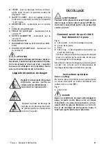
DECOLLAGE
........................................................................... 41
DEMONTAGE ........................................................................... 42
MONTAGE .............................................................................. 43
GONFLAGE ............................................................................ 43
RECHERCHE DES PANNES
............................................................ 44
ENTRETIEN ............................................................................ 45
INFORMATIONS CONCERNANT L’ENVIRONNEMENT
............................... 46
INFORMATIONS CONCERNANT LA DÉMOLITION
................................... 47
RECOMMANDATIONS ET AVERTISSEMENTS CONCERNANT L’HUILE
............. 47
MOYENS À UTILISER CONTRE LES INCENDIES
..................................... 48
LEXIQUE ............................................................................... 48
SCHEMA ELECTRIQUE GENERAL
.................................................... 49
SCHEMA CIRCUIT PNEUMATIQUE
.................................................... 49
Содержание PROMAXX 8150
Страница 17: ...17...
Страница 18: ...18...
Страница 33: ...33...
Страница 34: ...34...
Страница 50: ...50...
Страница 65: ...65...
Страница 66: ...66...
Страница 81: ...81...
Страница 82: ...82...
Страница 83: ...83 2 1 C A...
Страница 84: ...84 4 3...
Страница 85: ...85 5 6a 6 A B C mm A B E 8150 FI 8150 min 1570 750 870 max 1950 950...
Страница 86: ...86 A N F G H M C O E B Q L S R T U P V 7...
Страница 87: ...87 A B C D A A B C 10 8 9...
Страница 88: ...88 13 11 12 A B C L H...
Страница 89: ...89 16 14 15 G...
Страница 90: ...90 19 17 18 M C 20...
Страница 91: ...91 21 22a 22b N I...
Страница 92: ...92 25 23 24 F D...
Страница 93: ...93 28 26 27...
Страница 94: ...94 29 30 a b...
Страница 95: ...95 31...
Страница 96: ...96 32...
Страница 97: ...97 33 446694_2 3 ph...
Страница 98: ...98 33 430710C2 1 ph...
Страница 99: ...99 35 446726_2...
Страница 100: ...100 35 446724_1 AIR MOTOR...
Страница 101: ...101 35 453413 FI...
Страница 102: ...102 35 453414 FI AIR MOTOR...
Страница 103: ...103...
Страница 107: ......


