background image

B7

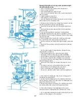
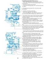
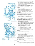
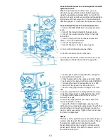
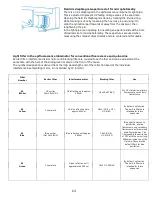
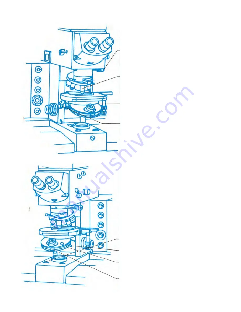
Transmitted-light microscopy with polarized light:
(A) with halogen lamp
⚪  Turn on halogen lamp with control transformer
⚪  Turn on relay (red dot)
⚪  Turn off Bertrand lens (pull out pin)
⚪  Turn off neutral density filter in the ocular body (black
dot not visible)
⚫  Insert analyzer and set to 0
⚪  Disengage the compensator
⚪  Pull out interference contrast main prism until it stops,
after loosening the clamping screw

⚫  Rotate to the 10x objective. Stress-free lenses must be
used for polarization-optical investigations
⚪  Switch off the exciter filter for transmitted-light (red
dot)
⚪  Switch off the neutral density filters for transmitted-
light (red dot)
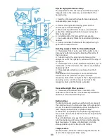
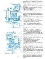
⚫  Line up the brightfield condenser. The brightfield
condensers described on page B2 are available in strain-
free versions (P). Turn lower condenser turret to the empty
opening (red dot)
⚫  Turn condenser fine feed to the central position and
raise condenser with coarse feed up to the stop
⚪  Set the collector for transmitted-light halogen lamp (red
dot)
⚪  Switch off the auxiliary optics for wide-field condenser
(red dot)

⚪  Set the photo system magnification changer to low
magnification (red dot, L)
⚪  Direct beam path to the camera (red dot, CAM)
⚪  Set beam at 20% to the body (red dot, CAM/PRO)
⚪  Set the phase ring knob to empty position (red dot)
⚪  Set the relay magnification changer to 1x (red dot)
⚪  On mirror housing 2, set rotary prism for transmitted-
light with halogen lamp
⚪  Switch off color filters for contrast fluorescence (red
dot)
⚪  On mirror housing 2, set excitation filter to red dot
⚪  Set sliding mirror to halogen lamp (red dot)
⚪  Turn on automatic zoom lighting (red dot)
⚪  Focus on a specimen with coarse and fine adjustment

⚫  Close field iris diaphragm, then focus its image with
condenser fine adjustment
⚫  Center field iris diaphragm in the middle of the field
with centering screws. Then open field iris diaphragm just
larger than the field of view
⚫  Swivel the polarizer into place. The interference colors
are visible when observing a birefringent specimen

⚫  Close the condenser iris diaphragm to the usual
2/3-open position, highlighting the interference colors

⚪  For comparative observations with normal light you can
switch out the analyzer or the polarizer

Содержание Univar

Страница 1: ...Reichert Univar Manual...

Страница 2: ......

Страница 3: ...Translated from the 11 1975 German language edition with slight modifications William R Porter San Marcos CA USA 2017 v 1 4...

Страница 4: ...nuals or literature were used nor indeed available in the production of this one This manual was translated purely for the use of myself it is being made available to the public free of charge for the...

Страница 5: ...rescence C5 Mixed illumination epifluorescence transmitted light darkfield epifluorescence transmitted light darkfield fluorescence C7 Mixed illumination epifluorescence transmitted light phase and an...

Страница 6: ...ral notes Observation tube F1 Rotating stage No 28 F1 Coarse drive stop F1 Condenser coarse and fine adjustments F1 Transmitted light objectives F2 Wide field plan compensation eyepieces F2 Relay syst...

Страница 7: ...ses is ensured for proper air circulation Remove the protective transport pieces The necessary hex wrench to unscrew the pieces is included a Remove the red plate covering the projection prism by unsc...

Страница 8: ...ith the condenser coarse feed to the lower stop position Hang the condenser turret transverse pin into the v shaped notch on top of the stand s condenser mount by tilting it back slightly hanging by t...

Страница 9: ...used for working with the XBO 450W Xenon lamp for the HBO 200W mercury vapor pressure lamp use filter holder H Replace the back panel of the mirror housing on the orientation pin located above and sec...

Страница 10: ...hree carrying handles can be unscrewed from the base of the microscope stand The threaded holes are provided with screw plugs Hand pads The magnetic hand rests are pushed on to the stand Eyepieces The...

Страница 11: ...ust collector for transmitted light halogen lamp set red dot Adjust the photo system magnification changer to low magnification L red dot Set the beam path to the camera red dot CAM Set the beam to 20...

Страница 12: ...0 90 Free working distance 0 29mm Use for all lenses from 4x to 100x When working with the 4x objective the condenser turret is set on 4 Recommended for all investigation methods where the immersion c...

Страница 13: ...light halogen lamp red dot Set the magnification lever in the photo system to low magnification red dot L Redirect the beam path to the camera red dot CAM Set eyepiece light to 20 red dot CAM pro Set...

Страница 14: ...rformance lamp Engage the neutral density filters for transmitted light when needed Evenly illuminate the field with the high performance lamp collector Immersion darkfield condenser N A 1 18 1 42 oil...

Страница 15: ...Switch off supplementary optics for widefield condenser red dot Adjust the transmitted light halogen lamp collector for even illumination red dot Set the photo magnification changer to L red dot Redir...

Страница 16: ...er lenses are also marked with the objective magnification The position 0 of the knob the red dot position provides an empty hole in the beam path Phase ring selection The phase annuli annular diaphra...

Страница 17: ...h off the auxiliary optics for wide field condenser red dot Set the photo system magnification changer to low magnification red dot L Direct beam path to the camera red dot CAM Set beam at 20 to the b...

Страница 18: ...r scale indicates degrees by 1 10 The polarization direction is north south at the 0 position A readjustment of the analyzer can be carried out as follows move the polarizer into place Hold the measur...

Страница 19: ...arse feed to the stop Switch off the auxiliary optics for wide field condenser red dot Adjust collector for halogen lamp red dot Adjust the photo system magnification changer to low magnification red...

Страница 20: ...rast main prism is inserted into the opening just above the front of the objective nosepiece and secured with the knurled screw at the side of the nosepiece To remove loosen the knurled screw and with...

Страница 21: ...er filter for transmitted light red dot Switch off the neutral density filters for transmitted light red dot Switch off the auxiliary optics for wide field condenser red dot Adjust the photo magnifica...

Страница 22: ...light with 4x objective use the frosted 4 filter on the lower condenser turret Blocking filter slide for fluorescence The blocking filter slide is inserted into the transmitted light optics carrier T...

Страница 23: ...slide and the immersion condenser Put UV shade tube on light well Set the collector of the high performance light on the mark Switch off the auxiliary optics for wide field condenser red dot Set off e...

Страница 24: ...ght fluorescence The blocking filter slide is inserted into the transmitted light optics carrier The empty slide is removed by pulling on the spring retainer at the front of the optics cavity The colo...

Страница 25: ...light halogen lamp red dot Set the photo magnification changer to red dot Direct the beam path to the camera red dot CAM Direct 20 beam to the body red dot CAM PRO For weak fluorescent objects select...

Страница 26: ...rings for other objectives are also marked with the objective magnification In the knob position 0 red dot the beam path is empty Ring aperture for contrast fluorescence There are specially designed...

Страница 27: ...ht blocking tube on light well Switch off exciter or color filter for transmitted light red dot Switch off neutral density filters for transmitted light red dot Adjust the halogen lamp transmitted lig...

Страница 28: ...for fluorescence studies Blocking filter slide for transmitted light fluorescence The blocking filter slide is inserted from the right in the transmitted light optics carrier The spring retainer on t...

Страница 29: ...desired excitation page C2 Adjust the photo magnification changer to low red dot L Direct beam path to the camera red dot CAM Direct 20 beam to the body red dot CAM PRO With weak fluorescent preparati...

Страница 30: ...ed size for microphotometry These apertures are used when measuring the smallest object details and are centered and focusable Filter Number Exciter Filter Interference Mirror Blocking Filter Use 40 w...

Страница 31: ...excitation page C4 Set the photo system magnification changer to low magnification red dot L Direct beam path to the camera red dot CAM Set beam to the body to 20 red dot CAM PRO For weak fluorescent...

Страница 32: ...ting up to approx 450nm 18x3 GG 9 G2 GG 9 VG By default no function The built in filters are intended for future expansion 49 Blue Blue exciter filter 18x3 BG 12 Blue reflective until approx 490nm 18x...

Страница 33: ...C6 Set the photo system magnification changer to low magnification red dot L Direct beam path to the camera red dot CAM Set beam to 20 red dot CAM PRO For weak fluorescent preparations set to to EYE...

Страница 34: ...usted at the same time with the help of the sliding lever located on the front of the attachment The number designation is derived from the long wavelength end of the reflection band of the individual...

Страница 35: ...to the stop A uniform liquid contact should occur between the immersion darkfield condenser and the specimen slide Turn the lower condenser turret to the empty opening red dot Rotate off the auxiliary...

Страница 36: ...the iris assembly towards or away from the operator C mixed light epifluorescence transmitted light darkfield Set up initially as in A for transmitted light darkfield with halogen lamp Then adjust as...

Страница 37: ...s for wide field condenser red dot Set collector for transmitted light halogen lamp red dot Adjust the photo system magnification changer to low magnification red dot L Direct the beam path to the cam...

Страница 38: ...iris diaphragm in the epifluorescence light pipe with the knurled ring and focus your image after loosening the hex shaft and moving forward or backward C mixed light Turn on the halogen lamp so that...

Страница 39: ...s for wide field condenser red dot Set collector for transmitted light halogen lamp red dot Adjust the relay magnification to low red dot L Direct beam path to the camera red dot CAM Set ocular light...

Страница 40: ...image and the transmitted light interference contrast image can be seen at the same time To better distinguish between of the two images you can rotate in a contrast filter for the halogen lamp Interf...

Страница 41: ...the photo magnification changer to low red dot L Direct light path to the camera red dot CAM Direct 20 beam to the ocular tube red dot CAM PRO Turn the phase ring knob to off red dot Set magnification...

Страница 42: ...Adjust the field iris diaphragm in the epifluorescence light pipe using the knurled ring and sharpen the iris image in the image plane by loosening hex post and sliding fore and aft C Mixed illuminati...

Страница 43: ...25 and on the right lamp house 50 The mirror knobs allow by simply switching a alternating the lighting between transmitted or epi illumination b mixing lighting from transmitted or epi illumination...

Страница 44: ...ional blue fluorescence e g with quinacrine S1 blue Exciter filter for blue brightfield 32x3 BG 12 h 2 Pcs S2 white Neutral density filters for comparison observation with visible light 32x2 N 6 T 1 6...

Страница 45: ...25 or 50 on the right This allows a alternative transmitted or epi illumination b mixed transmitted and epi illumination Use and combination of the exciter and blocking filter The exciter and blocking...

Страница 46: ...tfield is to be placed on the UV light shield tube 50x3 BG 12 h For immunofluorescence only with darkfield condenser S1 blue Exciter filter for FITC wideband 32x 2 5 FITC 490 2 GG 395 S2 blue Exciter...

Страница 47: ...lace a specimen on the stage After switching on the low voltage halogen lamp adjust for transmitted light brightfield microscopy Swivel the ground glass to off Turn the collector of the halogen lamp I...

Страница 48: ...D6 blank no content...

Страница 49: ...rprints on the quartz body will burn For reasons of operational safety change the lamp when the average lifespan is reached please observe the instruction manual for the lamp With the coin screw open...

Страница 50: ...he collector knob of the high performance lamp counterclockwise until it stops Redirect the microscopic optical path to view the lamp arc on the projection screen This is done through height adjustmen...

Страница 51: ...anged then the lamp may fail to ignite since the cables may short out to the metal housing Installation of the mercury vapor high pressure lamp HBO 200W 2 PLEASE NOTE Before opening the lamp house unp...

Страница 52: ...stage set the Univar to transmitted light brightfield with the high performance lamp for the light source Swivel ground glass off Turn off automatic zoom lighting and adjust the zoom handwheel to 63...

Страница 53: ...ves the 6V or 12V low voltage lamps It must be connected only to alternating current The primary voltage range is set by 100 125V or 200 250V in the factory The line cord into the power supply supplie...

Страница 54: ...of the ignition device The red button must be pushed in again reset before again turning on with the switch It is also advisable to take a break before re igniting so that the lamp can cool down The b...

Страница 55: ...ding to the modified power supply voltage and replace the button into the voltage selector The fuse to be used for line voltage of 110 125V is 10A for 150V is 6 3A and for 200 240V is 4A The main swit...

Страница 56: ...the lamphouse 50 comes on Then the lamp is lit with the red start button on the lamphouse 50 See instructions on page D10 The current controller is set at the factory for 25A and should not be adjust...

Страница 57: ...E1 E Trimatic Camera System Automatic camera 35mm 24 x 36mm format Camera with 4 x5 International film back Camera with Polaroid film cassette 3 1 4 x 4 1 4...

Страница 58: ...E2 blank no content...

Страница 59: ...via a cable that has two identical plugs One plug goes into the socket on the back of the microscope the second plug is connected to the back of the control unit The connectors will only connect in t...

Страница 60: ...mally set to 220V When switching to a different voltage the inner head of the voltage selector is pushed in and removed after a quarter turn of the screw counterclockwise With a coin or screwdriver bl...

Страница 61: ...l film and 70mm film This position is kept free for a not yet specified camera format The eyepiece mounts are adjusted by turning so that the lines of the double circle appear separated and as sharp a...

Страница 62: ...rned to the left CCW If the pointer is in the left red field then the exposure time is too short you must turn to the right CW The bandwidth of the green field is 3 DIN In the case of very dark specim...

Страница 63: ...rt and an exposure adjustment is no longer possible Press the fluor key and the pointer will move to the right so that you can balance up to 8 hours During the measurement of the long exposure times t...

Страница 64: ...shutter to trigger any exposure time The shutter white indicator light remains open until the button is released again Interruption of exposure The stop button is used to interrupt an ongoing exposure...

Страница 65: ...up to the shortest of 1 125 sec The operation is described in a separate manual Brightness dependent voltage According to the brightness of the microscopic image the output voltage range is 0 5V for...

Страница 66: ...olaroid Roll Film Cassette 3 1 4 x 4 1 4 or the Roll Film Cassette Super Rollex 56 x 72mm can only be installed after removing the spring back The two springy levers which are located on the removable...

Страница 67: ...nserted into the empty side of the cartridge chamber The beginning of the film is pushed into the slot of the take up spool until the teeth get hooked on the second perforation hole Now turn the take...

Страница 68: ...r of images set on the external counter must not allow more exposures than the cassette counter so that the film transport is not disturbed If necessary set to an exposure less After all exposures are...

Страница 69: ...oosening the fastening screw of the specimen slide positioner it can be removed from the stage table Coarse drive stop The adjustable coarse focus drive stop limits the height setting of the stage tab...

Страница 70: ...nings Plan Plan achromatic lens Plan Apo Plan apochromatic objective lens Oil Glyz for oil or glycerin immersion Iris built in iris diaphragm 100x 1 25 objective magnification 100x numerical aperture...

Страница 71: ...of the image are fully preserved The zoom system is especially useful for format filling photomicrography for an ideal adaptation to the specimen size Slider slot An opening in which you can insert a...

Страница 72: ...her with the lighting setup this system achieves automatic K hler illumination The light coming from the lamp is optimally utilized and the conductance i e the product of the field and aperture is hel...

Страница 73: ...if absolutely necessary use pure xylene The often still lingering coating can be removed with a piece of polystyrene foam However the previously used solvents must have evaporated completely It is pre...

Отзывы: