


MO 3, MO 3.3, MO 3.4, MO 3.5
27
C.) Adjustment of the Capacitive Transmitter Served as a Feedback of the Position Controller (EA MO
with controller
)
While checking or adjusting the output signal of 4÷20 mA follow these steps:
•
Disconnect the circuit on the terminals 81 and 82 removing the jumper.
•
Connect power supply to the terminals 1 and 61.
•
Disconnect the control signal from the terminals 86/87 and 88.
•
Put the actuator to the direction "OPEN" or "CLOSE" with the handwheel or by connecting power supply to
the relevant terminals for the direction "OPEN", or for the direction "CLOSE".
•
Connect a mA meter of precision class 0,5 (e.g. digital) and loading resistance lower than 500
Ω
on the
terminals 81,82.
•
Follow the procedure for the version without any power supply described in the previous chapter A.
•
Having the transmitter adjusted put the jumper again on the terminals 81 and 82 in case that the output
signal wont be used (the circuit through the terminals 81 and 82 should be closed).
•
Connect the control signal to the terminals 86/87 and 88.
The user has to arrange grounding of the 2-wire circuit of the capacitive transmitter to the electrical
ground of a joined controller, computer, etc. The grounding should be performed only in one place in
any part of the circuit outside the electric actuator!
With the version with regulator when the feedback from the CPT transmitter is used; at using the input signal,
this signal isn’t galvanic insulated from the output signal !
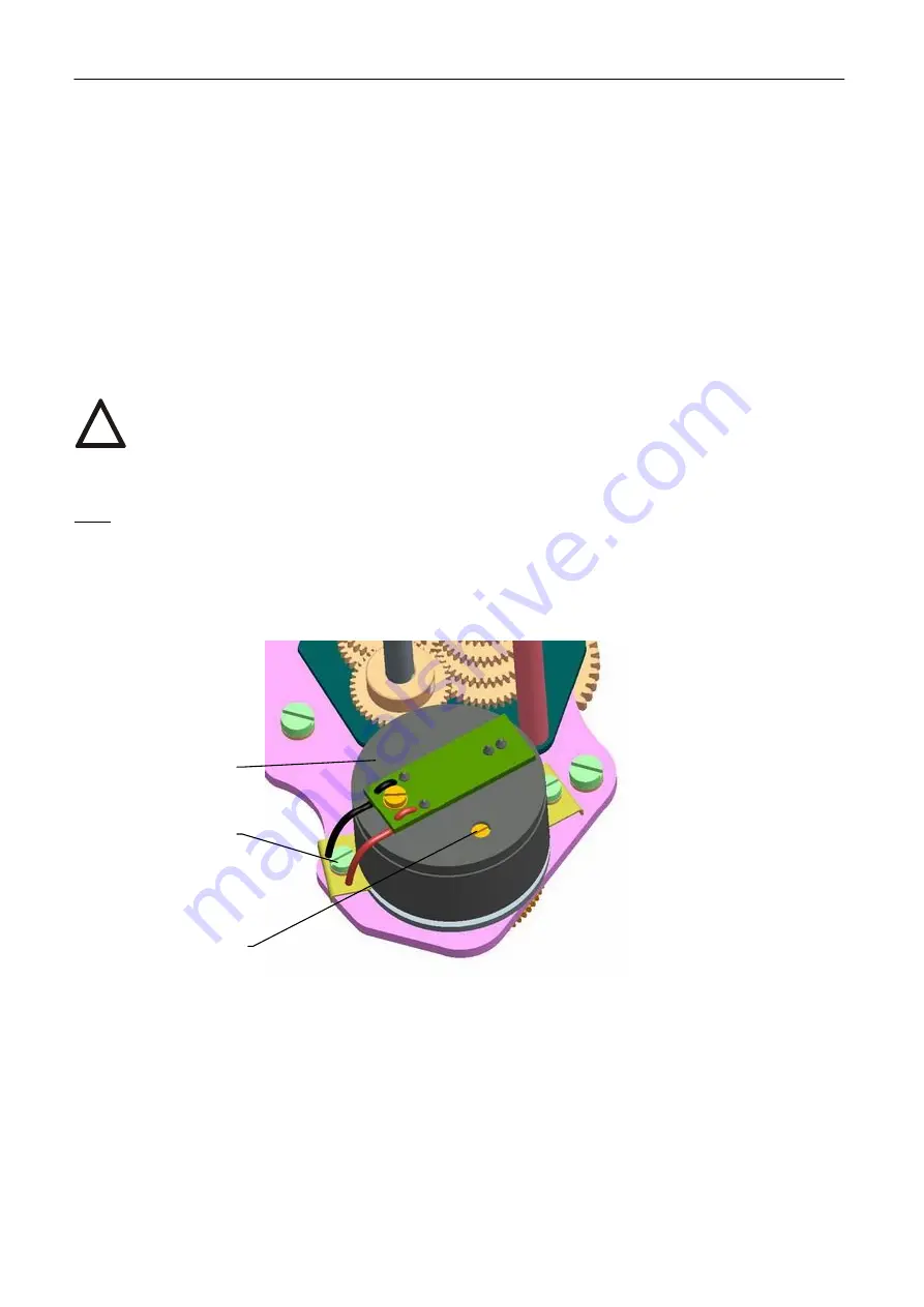
Note:
The trimmer (97)(Fig.12) ) can be used to adjust the output signal of the capacitive transmitter to any value of
operating revolutions in range from ca 50% up to 100% of the max. value of the operating revolutions on the
competent degree according to table 3.
!
Fig.12
96
95
97
Содержание MO 3
Страница 35: ...MO 3 MO 3 3 MO 3 4 MO 3 5 33 7 Enclosures 7 1 Wiring diagrams Wiring diagrams MO...
Страница 36: ...34 MO 3 MO 3 3 MO 3 4 MO 3 5...
Страница 37: ...MO 3 MO 3 3 MO 3 4 MO 3 5 35 Wiring diagrams MO with controller...
Страница 41: ...MO 3 MO 3 3 MO 3 4 MO 3 5 39 4 x tooth F10 shape D F10 shape C DIN 3338 F10 shape E ISO 5210...
Страница 42: ...40 MO 3 MO 3 3 MO 3 4 MO 3 5 Mechanic connections for EA MO 3...
Страница 43: ...MO 3 MO 3 3 MO 3 4 MO 3 5 41...
Страница 45: ...MO 3 MO 3 3 MO 3 4 MO 3 5 43 Dimension drawings for EA MO 3 5...
Страница 46: ...44 MO 3 MO 3 3 MO 3 4 MO 3 5 Dimension drawings for EA MO 3 4...
Страница 47: ...MO 3 MO 3 3 MO 3 4 MO 3 5 45 Dimension drawings for EA MO 3 3...
Страница 50: ...48 MO 3 MO 3 3 MO 3 4 MO 3 5 Mechanic connections for EA MO 3 4 with connect adapter...
Страница 51: ...MO 3 MO 3 3 MO 3 4 MO 3 5 49...
Страница 53: ...MO 3 MO 3 3 MO 3 4 MO 3 5 51 Mechanic connections for EA MO 3 5 with connect adapter F14 shape A ISO 5210...