background image

130-01 Operations 


Refraction Technology, Inc. 


 26 


2.2


Establishing Minimal Hardware Connections 

These instructions cover the hardware and connections needed to perform 
the recorder operations described in the rest of this section.  

To perform the system power-up, you need the following hardware:  

ƒ


A 130-01 DAS. 

ƒ


A personal computer; either a PDA, laptop, desktop, or other appropriate control 

interface, including a dumb terminal. 

ƒ


An external 12 volt power supply; you can use a 12 volt car battery. 

ƒ


A cable to connect the control interface to the recorder (you can use a 130-8262 

with a Ruggedized PDA). 

ƒ


One cable to connect the power supply to the recorder (if you are using an Auxiliary 

Power Subsystem, you can use a REF TEK PT07A12-4S connector with a power 
cable).  

 
Note: A sensor is not required for this exercise as the noise pick-up at the open 

input channel connector is sufficient. If you do have a sensor you must make the 
channel connections as described in the manual for your particular type of 
recorder and sensor.  


Assuming you have obtained or made up all the required cables, proceed to 
make the following hardware connections:  

1.


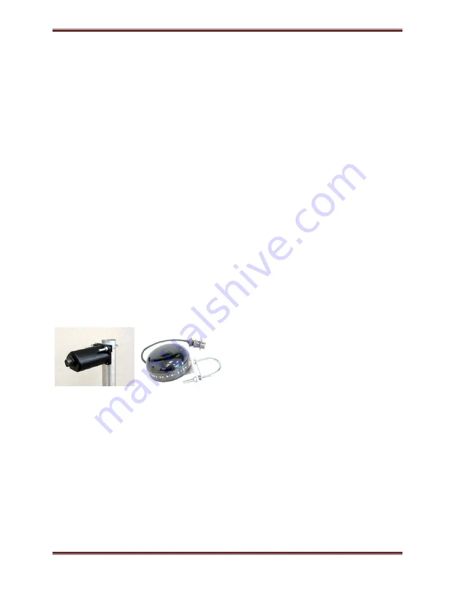
Install the 130-GPS with a clear view of the sky. 

WARNING:   DO NOT install the GPS at the top of the pole or antenna. 


2.


Secure the appropriate cable from your PDA or PC control interface to your 
recorder. In most cases you’ll connect the 130-8025 cable connector to the 

SERIAL connector on the recorder and secure the other end of that cable to the 
serial port of your PDA control interface. 

3.


Secure the PT06A12-4S connector on your external power cable to the POWER 
connector on the recorder. Secure the other end of the power cable to your 12 

volt power supply so that connector pins A and B are both are at +12 volts and 
pins C and D are the return lines. 

4.


Secure the PT06A14-19S connector from each sensor cable (2 each for 6 channel 

recorder) to each channel connector on the case top. 

5.


Secure the PT06A12-8S connector of the 130-8015 cable for the GPS to the GPS 

connector on the case top. 

X

Содержание 130-01

Страница 1: ...ations Startup 10 30 2008 CPU 2 9 1 This REF TEK manual provides startup and basic operating procedures for the 130 01 and its related family of products Internal cable drawings are also provided along with guidelines for initial communication and installation ...

Страница 2: ...rved No part of this manual may be reproduced copied or transmitted in any form outside the approved recipient s organization without written permission from Refraction Technology Inc Printed in USA Refraction Technology 1600 Tenth Street Suite A Plano Texas 75074 Tel 214 440 1265 Fax 972 578 0045 www reftek com ...

Страница 3: ...s 130 01 Startup manual provides a detailed overview of the command line operations and setup of the 130 01 It covers the following broad operational topics Overview Connections Operation with PFC Port Settings and Power Considerations Modem Setup Periodic Maintenance Logfile Example ...

Страница 4: ...he resulting problems with compatibility due to memory layout signal structuring and power requirements Refraction Technology cannot guarantee a CF card will work in a REFTEK data recorder unless it is sold through REFTEK itself REFTEK ensures compatibility through communications with CF manufacturers and rigorous in house testing Some CF manufacturers refuse to provide adequate information or fac...

Страница 5: ...re Updating firmware in a 130 DAS requires the presence of a firmware file on an installed Compact Flash device 1 On power up the 130 checks the Compact Flash for the presence of main s3 in the root directory 2 If the main s3 file is present on the Compact Flash the 130 a Reads the file b DELETES the file c Re programs the internal flash memory Note DO NOT DISTURB THE UNIT DURING THIS PROCESS Foll...

Страница 6: ...turns to normal messaging b If you are remotely connected to a 130 DAS via telemetry mode 1 If you are connecting remotely by a TCP connection a First connect b Discover the unit c Acquire status 2 Issue a reset command from the Status screen 3 Delete the unit from the Station List screen 4 Wait at least 5 minutes 5 At the Connections screen reconnect id using a TCP connection issue a Station Disc...

Страница 7: ...mal numeric value i e 84 represents hexadecimal 84 132 decimal When the contents are capital letters it represents a named ASCII control character i e SP represents a space character CR represents a carriage return character and LF represents a line feed character MSB Most Significant Byte of a multi byte value MSbit Most Significant Bit of a binary number LSB Least Significant Byte of a multi byt...

Страница 8: ... Doc 130 RT526 RT526rB01 pdf RT527 Sensor Control Board Optional Doc 130 RT527 RT527rB01 pdf RT535 Mass Memory Board Optional Doc 130 RT535 RT535rB01 pdf Optional Manuals Number PDF file SNDP Reference Guide Doc SNDP Ref SNDPRef pdf SNDP Installation and Users Guide Doc SNDP Install SNDPUser pdf RTPD Installation and Users Guide Doc RTPD RTPD pdf RTP Protocol Doc RTP RTP pdf RT_View Users Guide Pa...

Страница 9: ... REF TEK product updates please spend a couple of minutes to register with the REF TEK customer support team To register either email to updates reftek com giving us your name and REF TEK product you currently have or fill out our online registration form at www reftek com registration Once we register your contact we will only send necessary notifications via email The same notifications will be ...

Страница 10: ...r operation 13 1 6 2 Power Considerations 15 1 7 Port Settings Modem Communications 16 1 7 1 Control Serial Port 16 1 7 2 Serial PPP Port 17 1 7 3 NET Port 17 1 8 Hardware Modularity 18 1 9 Frequently Asked Questions 20 1 10 Warranty Statement 22 1 11 Warranty Non Warranty Service 23 1 12 Static sensitive device protection 24 2 Startup 25 2 1 Getting started with your 130 01 DAS 25 2 2 Establishin...

Страница 11: ... PPP 56 3 5 2 Data transfer through PPP real time 58 3 6 PC Communication Setup 59 3 6 1 130 DAS modem communication 59 3 6 2 Install modem 60 4 Periodic Maintenance Operations 63 4 1 Introduction 63 4 2 Replacing the Compact Flash 64 4 3 Connector Assembly Maintenance 67 4 4 Periodic Maintenance checks 69 4 5 Replace CPU Battery 130 01 3 and 130 01 6 70 4 6 Disassembly of the 130 for service 71 4...

Страница 12: ...placing an RT527 83 5 1 Overview 83 5 2 Installation 84 5 2 1 Upgrade 86 5 2 2 For a new installation 86 5 3 RT527 Scope 88 5 3 1 Channel Connector Signals 88 5 3 2 Sensor Test Signals 89 5 3 3 Auxiliary Channels 89 6 Logfile Example 91 6 1 Timing examples 91 6 2 System information 95 6 3 Acquisition Information 98 6 4 Disk Access Information 100 ...

Страница 13: ...4 Format Disk 35 Figure 15 Set Acq Delay 36 Figure 16 Write WP 37 Figure 17 Load LP 38 Figure 18 Add Modem 42 Figure 19 Have Disk Modem 43 Figure 20 Select Generic 43 Figure 21 Select Port 44 Figure 22 Modem Success 44 Figure 23 Phone and Modem Options 44 Figure 24 Modem Properties 45 Figure 25 Control Panel 46 Figure 26 Make New 46 Figure 27 Incoming Connect 47 Figure 28 Allow Incoming Virtual 48...

Страница 14: ...m 61 Figure 46 New Modem 62 Figure 47 Modem Properties 62 Figure 48 Handle drive 65 Figure 49 Install Drive 65 Figure 50 Compact Flash 66 Figure 51 PTO Connector 68 Figure 52 130 01 Boards Stack 69 Figure 53 130 01 3 Bill Of Materials 72 Figure 54 Tighten Pattern 76 Figure 55 RT527 SCB 83 Figure 56 Unbolt 130 Case 84 Figure 57 Remove 130 Top 85 Figure 58 Stack Screws 85 Figure 59 Install O Ring 86...

Страница 15: ...unctions pin out and associated cables drawings General 130 01 DAS control considerations and operation Port settings and modem communications Hardware modularity Frequently Asked Questions about the 130 01 WARNING A 130 DAS is shipped pre configured with a default IP address Be sure to change this address before connecting the DAS to an Ethernet port WARNING The 130 DAS uses a 10BaseT Ethernet ch...

Страница 16: ...130 01 Operations Refraction Technology Inc 2 ...

Страница 17: ...nels With Communications A D Converter Type modulation 256 KHz base rate 24 bit output resolution Channels 3 or 6 channels Input Impedance 2 Mohms 0 002 µFd differential x 32 25 Kohm 0 002 µFd differential x1 Common Mode Rejection Greater than 70 db within 2 5 VDC Gain Selection x1 and x32 Input Full Scale 20 VPP x1 0 625 VPP x32 Bit Weight 1 589 µvolts x1 49 nV x32 Noise Level 1 count RMS at 50sp...

Страница 18: ...d times and lengths Event Trigger STA LTA with advanced features including bandpass filter LTA hold etc Level Trigger Absolute value user selectable g or of full scale or counts including bandpass filter External Trigger External pulse on trigger input line Recording Capacity Battery Backed SRAM 5 Mbytes Flash Disk 4 Gbytes with two CFII cards 8 Gbytes also available Recording Format Format PASSCA...

Страница 19: ... data recorders The modular design of their hardware and software allows you to reconfigure them for various types of applications both short and long term Some specific uses include the following Collecting seismic data from earthquakes and micro seismic events in local regional and global studies Broadband Aftershock Active Source Micro Zonation Survey Site Noise Survey ...

Страница 20: ... unit through one power connector Hardware connection shows typical hardware connection for the 130 01 DAS The following chart details individual connectors and REF TEK cable numbers Recorder faceplate connector Connector and Cable 130 Pin Pin Desc Electrical Desc Voltage Range Power PT06A12 4P A 12 VDC Input 10 15 VDC Cable 130 8075 B 12 VDC Input 10 15 VDC C DGND Power Return D DGND Power Return...

Страница 21: ...K PWR Output2 5 Volts3 1 5 3 GPS Connector The GPS connector allows an external clocking device such as the REF TEK 130 GPS Global Positioning System clock This connector provides power and serial connections to the 130 GPS Receiver via the 130 8015 cable See the 130 GPS manual for more information Recorder Faceplate Connector Connector and Cable 130 Pin Pin Desc Electrical Desc Voltage Range GPS ...

Страница 22: ...ect using FTP and or the command socket However the 130 DAS unit restricts the external IP addresses from which it will accept connections to the equivalent of a Class C subnet containing the RTP host If no RTP host is set for an interface no connections can be established to the unit from outside its subnet WARNING The 130 DAS uses a 10BaseT Ethernet chip The 130 DAS Ethernet port will not work w...

Страница 23: ... Ethernet3 J ENET TX Output Ethernet4 K ENET RX Input Ethernet5 L ENET RX Input Ethernet6 M ENETPWR PWR Ethernet7 12 Volts8 N DGND P DGND R DTR A Output RS232 5 Volts S TRIGOUTB Output Tristate 0 5 Volt Pulse T TRIGINB Input 0 5 Volt Pulse U 12VDC Input 10 15 VDC9 V OSC Output Tristate10 0 5 Volts 1 VDC Controlled by software 2 Volts Protected by self resetting fuse 3 Ethernet Transformer coupled ...

Страница 24: ... socket to designate the unit as only a three channel Signals from an external sensor enter the 130 01 DAS through the channel input connector labeled CH 1 3 Six channel 130 DAS units 130 01 6 and 130 02 6 use a second input connector labeled CH 4 6 Channel connectors also provide pins for calibration signals to be sent to a sensor Note The 130 01 DAS Station Info PDA display will show how many ch...

Страница 25: ...3 Out Calibration Enable active low OC 4 6 L CalEn 123 Out Calibration Enable active high OC 5 6 M Center 123 Out Center Enable active low OC 4 6 N CalSig 123 Out Calibration signal 5 Volts 6 P Aux1 In Aux Mass Position channel 1 10 Volts 6 R Aux2 In Aux Mass Position channel 2 10 Volts 6 S Aux3 In Aux Mass Position channel 3 10 Volts 6 T DGND Digital Ground U Center 123 Out Center Enable active h...

Страница 26: ... Calibration Enable active low OC 4 6 L CalEn 456 Out Calibration Enable active high OC 5 6 M Center 456 Out Center Enable active low OC 4 6 N CalSig 456 Out Calibration signal 5 Volts 6 P Aux4 In Aux Mass Position channel 4 10 Volts 6 R Aux5 In Aux Mass Position channel 5 10 Volts 6 S Aux6 In Aux Mass Position channel 6 10 Volts 6 T DGND Digital Ground U Center 456 Out Center Enable active high O...

Страница 27: ...structs the 130 01 DAS how to perform system functions it is called the PDA Field Controller program PFC_130 for a PDA device and is documented in the PFC_130 Users Guide 130 PFC 001 REF TEK also provides RTCC software for command and control with a PC or workstation Also Refraction Technology maintains release notes on its ftp and WWW site 1 6 1 General Recorder operation Refraction Technology pr...

Страница 28: ... records data Detailed explanations and methods for using all 130 01 DAS unit parameters including datastreams and triggers are provided in subsequent sections in this manual Refraction Technology pre sets and tests the hardware of each 130 01 DAS before you receive the unit to ensure that it performs as specified The 130 01 DAS units do not require hardware adjustments for normal operations You m...

Страница 29: ...ort connector 5 VDC or 12 VDC Also 12 VDC is available on the two channel connectors In general perform the following to ensure a sufficient power supply 1 Use the specification data and add the maximum current draw for the 130 01 DAS and each peripheral that uses the same power supply to obtain the maximum total current they will draw at any given time then add at least 25 2 Check your power supp...

Страница 30: ...ction 2 of this manual To setup port connections refer to the PFC_130 Users Guide Note With a modem the user can provide a user defined init string that will be sent to an externally attached modem at powerup 1 7 1 Control Serial Port Each 130 01 unit provides two bi directional asynchronous serial ports The first of these ports is accessible at the Serial connector on the 130 01 DAS unit s facepl...

Страница 31: ...0 baud no parity 8 data bits and 1 stop bit Hardware Location This port is accessible at the Serial connector on the faceplate Other Features Software controlled output 1 7 3 NET Port In addition to the serial port each 130 01 DAS provides one Ethernet port This port accessible at the communications Net connector on the 130 01 DAS unit s faceplate has the following primary functions and characteri...

Страница 32: ...or 130 01 3 and 130 01 6 models ONLY RT526 B01 Interface Board located in the well Dual Compact Flash 3 A D Converter RT505 B05 A D Converter Allows 1 3 Channels for 130 01 3 and 130 01 6 24 Bit ADC Channels 3 each board OPT 4 A D Converter RT505 B06 Lightning Protection Adds 4 6 Channels to 130 01 6 and 130 02 6 Input Pre Amplifier Digital Anti Alias Filters OPT 5 Sensor Control Board RT527 B01 M...

Страница 33: ...tors from the primary system bus Note 130 01 3 same as figure above without RT505 B06 A D Note Optional board Note For some DAS units an EMI protective shield has been added to make the unit CE compliant Care should be taken in removal when servicing the unit RT526 B01 Well Disk drive 130 8013 Case Top 130 9001 Cap 130 9002 Case Bottom Sea l Bla ck Well PCB 130 9000 130 9003 RT505 B05 RT520 B01 RT...

Страница 34: ...te for all streams 1000 500 250 125 50 and 25 Group Two The following rates may be recorded in any combination within all streams 200 100 40 20 10 5 and 1 Case Description Example of Selection of a sample rate from Group One When the user activates any of the other data streams the sample rate chosen must be the SAME Selection of 125 SPS for Data Stream 1 This means that when Data Stream 2 is acti...

Страница 35: ...ector 1 Ethernet 10 Base T 2 Serial PPP Asynchronous RS 232 SERIAL Connector 3 Serial Asynchronous RS 232 for command and control ONLY The 130 01 DAS can be used with a spread spectrum radio by direct connection over serial PPP to the spread spectrum radio no router required The 130 DAS supports all types of Telemetry configurations It is also possible for the serial line mode to be used with a mo...

Страница 36: ...the customer See Warranty Non Warranty Service for equipment return instructions In the event Refraction Technology supplies other manufacturers equipment with systems this equipment will have the same warranty as stated above provided the Refraction Technology nameplate is on the equipment otherwise the equipment will carry the warranty of the original manufacturer only It is the policy of Refrac...

Страница 37: ...hnology Inc 1600 Tenth Street Suite A Plano Texas 75074 USA Voice 214 440 1265 Fax 972 578 0045 EMAIL support reftek com FTP ftp reftek com WWW http reftek com 1 Supply the indicated information at time of contact Description of Problem Type of Instrument Model No Serial No 2 Package the equipment safely preferably using the original packing materials Include the RMA on the outside of the shipping...

Страница 38: ... REF TEK circuit boards the handler and the work bench are grounded This is usually done via a grounding mat on the bench which is ultimately grounded to the building ground and also attached to the handler 2 When shipping individual boards they must be wrapped in anti static protection either anti static bags or boxes REK TEK can supply these if requested 3 Failure to protect against static incre...

Страница 39: ...connections for the recorder in order to perform an initial system power up External cable list Minimum hardware connection and power up A procedure to specify an abbreviated set of operating parameters start and verify data acquisition and save collected data to a file These instructions do not provide you with the detailed comprehensive information you need to prepare your recorder for field dep...

Страница 40: ...e the channel connections as described in the manual for your particular type of recorder and sensor Assuming you have obtained or made up all the required cables proceed to make the following hardware connections 1 Install the 130 GPS with a clear view of the sky WARNING DO NOT install the GPS at the top of the pole or antenna 2 Secure the appropriate cable from your PDA or PC control interface t...

Страница 41: ...m the 130 Flash kit Note Remember to hold the Compact Flash only by its edge as shown below 3 Install the Compact Flash as shown above 4 With the Compact Flash in position in the guide rails lightly press the drive as shown below to lock into position Note The 130 01 DAS is not shipped with the Compact Flash installed ONLY remove the Compact Flash by holding the silver tape to prevent damage to th...

Страница 42: ...he screen it was last displaying when it was last powered down Reset the PDA to the PFC_130 icon by touching the Home button on the PDA 2 Turn on the supply to apply voltage to the 130 01 Recorder and to your control interface Note Wait at least 20 seconds and the LCD display should display the following Figure 3 LCD Display Unit ID Firmware Version Firmware Date ...

Страница 43: ...t of the oscillator 5 The 30th value is also used to determine the phase error of the internal 1 Hz 6 The oscillator is voltage controlled and an adjustment is made to the controlling D A value to zero out the oscillator drift and also to correct for oscillator phase error In sleep mode the 130 01 1 Puts the GPS into binary mode 2 Then into Push to fix mode via serial commands at which point the G...

Страница 44: ...e from the pull down menu 3 At the Main PFC menu tap the Control window to establish a connection 4 A connect to DAS menu will display initializing the connection to the DAS Figure 5 PFC Control 5 Tap the Status window to check the current status of the 130 01 DAS Figure 6 PFC Status 6 Two more screens will open to verify and load status information Figure 7 PFC Load Status ...

Страница 45: ...quisition button Main input voltage Backup battery voltage and update display Active Channels 1 6 Active Datastreams and Net status DAS time C Continuous I Time Interval E Event L Level T Time List K Cross X External Start ON Acquisition start requested and acquisition is ON Start OFF Acquisition start requested and acquisition is OFF Stop ON Acquisition stop requested and acquisition is ON Stop O...

Страница 46: ...inuously Cycled After the first GPS wake cycle the GPS is powered OFF for 20 minutes The GPS is then powered ON for one wake cycle and then powered OFF for 20 minutes again The 130 repeats the 20 minutes OFF and ON for 1 GPS wake cycle while in the Duty Cycle mode OFF The 130 will turn the GPS ON for the first GPS wake cycle After the first GPS wake cycle the GPS is powered OFF and never powered O...

Страница 47: ...s to one datastream using the disk as a destination for the data 1 Create a new configuration for the 130 01 DAS starting with the New menu Figure 9 PFC New Configuration 2 Create and name the new configuration as Test 3 Tap OK to create the configuration and return to the Configuration Manager Menu Figure 10 New Configuration 4 Edit the 130 01 DAS configuration by tapping the Edit button ...

Страница 48: ...ils Figure 12 Channel Details Edit Streams 6 Tap Streams to enter Stream details and set the data destination to disk D Figure 13 Stream Details 7 Set the record length to be 300 seconds and leave time as default 8 Change to the Configuration Manager menu and save the configuration 9 Send the parameters to the 130 01 DAS by using the Send to DAS command from the Configuration Menu Configuration St...

Страница 49: ...Tap the Format Disk menu on the Control menu 3 Select the Disk to be formatted 4 Select the Start button to start the format or the Cancel button to cancel the format and return to the Control menu 5 Confirm the format by selecting the OK button 6 When the format is complete the submenu displays Completed or Error 7 Select the Done button to return to the Status menu 4 ...

Страница 50: ... Status menu 3 If a delay is desired enter a delay time or approve with the OK button Figure 15 Set Acq Delay 4 After some period of time 5 minutes or more stop acquisition on the 130 01 DAS Start OFF Acquisition start requested and Stop ON Acquisition stop requested and Start ON Acquisition start requested and Stop OFF Acquisition stop requested and acquisition is OFF acquisition is ON acquisitio...

Страница 51: ...e parameter file is always saved with Acquisition ON To write a parameter file from the DAS to each disk 1 Select the DAS LP WP button Be sure the Acquisition is ON 2 Select the Write button to write the DAS parameter file Figure 16 Write WP 3 Select the OK button to approve the write operation Note It is also possible to Write or Load a parameter file during the DAS configuration operations by us...

Страница 52: ...nd then the DAS will search for a file named 130_0000 CFG To Load a parameter file from a DAS disk to the DAS 1 Select the DAS LP WP button 2 Select the Load button to load the DAS parameter file Figure 17 Load LP 3 Select the OK button to approve the load operation Note It is also possible to Write or Load a parameter file during the DAS configuration operations by using the DAS LP WP command on ...

Страница 53: ...backup power Acceptable Range 10 15Volts Backup Range 2 2 3 6 Volts Acquisition Status Stream Indicator C Continuous L Level I Time Interval E Event T Time List K Cross X External V Vote F irmw are V ersion Date Fi rm w are Uni t ID F irmw are V ersion Date Fi rm w are Uni t ID Used MB Total AvailableMb Date Time Interna l temperature GPS Status GPS Position Main po we r B attery backuppow er Requ...

Страница 54: ......

Страница 55: ...PC can be accomplished by using either Direct PPP connection over a direct serial link with a serial cable or serial radio Modem PPP connection over a serial link with the 130 DAS Modem or by using the Modem connector on the 130 SM An optional external modem can also be used with the 130 NET connector for serial communication ...

Страница 56: ...rive however there is no reason to access or make changes to it This information file is not needed when using a standard telephone modem If you do not need to install the Generic Null modem skip the next section To add a generic null modem perform the following instructions 1 From the Control Panel select the Phone and Modems icon 2 Select the Modems tab 3 Select the Add button Figure 18 Add Mode...

Страница 57: ...ist 6 In Install New Modem click Have Disk Figure 19 Have Disk Modem 7 At the Install From Disk window in the Copy Manufacturer s files from text box type C reftek 8 Click OK when ready 9 At the Install New Modem window under Models select Generic NULL Modem 10 Click Next when ready Figure 20 Select Generic ...

Страница 58: ...ady Figure 21 Select Port Note If the Digital Signature Not Found warning appears select the Yes button and proceed 13 The Install New Modem window will display Your modem has been set up successfully 14 Click the Finish button Figure 22 Modem Success 15 At the Phone and Modems Options window select the Properties button Figure 23 Phone and Modem Options ...

Страница 59: ... direct connection to a 72A with the RT422 board the RT422 board is configured at the factory to 9600 but can be changed Reference the RT422 Asynchronous Serial Communications Card Board Document for additional information on the jumper configurations that support the baud rate setting For connection to a DAS thru a radio or other equipment consult their operations manual 17 Click OK when ready Fi...

Страница 60: ...emote Access Services RAS 1 Using standard window operations click Start Settings Control Panel 2 Double click the Dial up Connection Icon Figure 25 Control Panel Note Windows XP uses a New Connection wizard 3 Double click the Make a New Connection Icon Figure 26 Make New Network and Dial up Connection ...

Страница 61: ...8 Refraction Technology Inc 47 4 Select the Next option screen 5 Select Accept incoming connections and the Next button 6 Check the Generic Null Modem option 7 Click the Next button when ready to continue Figure 27 Incoming Connect ...

Страница 62: ...9 Click the Next button Figure 28 Allow Incoming Virtual 10 Select the Add button to add a new DAS connection Figure 29 Add DAS User Note When a DAS unit is setup and is connected to a PC an account must be created and added The account Username MUST be the particular DAS unit ID that is directly connected to the PC ...

Страница 63: ...lude the alpha characters das and number sign If the DAS unit ID is hex the letters should be in uppercase ONLY i e 9AB2 not 9ab2 8 total characters only 12 Click in the Full Name and fill in any name or leave blank 13 For the Password setting you must use the Username i e das 9066 14 Next Confirm Password by re typing the password Note The Password settings are case sensitive 15 Select the OK but...

Страница 64: ...coming TCP IP Properties enable Allow callers to access my local area network Figure 32 Remote Access 20 Enable Specify TCP IP address 21 In the From text box type a generic IP address where From IP address PC s PPP IP address 22 In the To text box type a destination IP address where To IP address Range of IP address for Serial PPP pool 23 Click OK when ready 24 Click Finish after naming the conne...

Страница 65: ... Windows Control Panel For Windows 2000 Start Settings Control Panel Administrative Tools Services For Windows XP Start Settings Control Panel Administrative Tools Services Component Services A shortcut to the control program has also been placed at Start Programs Refraction Technology RTP Services Services The shortcut can be copied to the windows desktop by dragging it to the desktop while holdi...

Страница 66: ...l program 2 Double click the Services icon to open the windows services process window Figure 33 Services 3 Highlight and select the Routing and Remote Access service 4 Start the service by using the Action pull down or using the start icon on the task bar Figure 34 RAS started 5 Close the control program Start icon ...

Страница 67: ...sition System family The unit looks similar to the 130 GPS except it has the 130 Modem label on the end of the unit and two wires connected as shown below Figure 35 130 Modem 3 3 2 DAS Setup This Section explains the REF TEK 130 Modem when it is used with the REF TEK 130 family The 130 Modem is an optional external modem A user should be familiar with whatever REF TEK host system is in current use...

Страница 68: ... an available phone line connection The REF TEK 130 8154 130 Modem to DAS cable referred to above is wired as follows Modem Connector PT06A1210P SR 130 Net Connector PT06A14 19S Signal Phone Line Cable PIN A PIN A RX PIN B PIN B TX PIN C PIN C RTS PIN D PIN D CTS PIN E PIN E GND PIN F PIN F CCD PIN G Phone TIP Red 2 PIN H Phone RING Green 3 PIN J PIN G 5V PIN K PIN M 12 V No additional cables are ...

Страница 69: ...s It is a single design that includes a DSP data pump a modem controller on chip RAM and ROM an analog front end AFE a DAA and analog output Note The 130 8137 modem cable is used with the 130 01 when supplied with an internal modem 3 4 1 Modem features The SLM2456 accepts standard modem AT commands and provides connect rates up to 56 33 6 14 4 kbps full duplex over the Public Switched Telephone Ne...

Страница 70: ... connected the user MUST use these settings to configure the modem 1 Use the Control menu Net button to assign Serial PPP parameters for the modem Figure 36 PFC Control 2 Click the Line Mode type of serial connection pull down arrow and select the AT Modem option from the pull down Note Direct Connection to a PC or router or FW in point to point mode FW Multi Connection to a Freewave operating in ...

Страница 71: ...igurations at the same time and only send them to the DAS once If using AT Modem Line Mode 1 Select the Modem button to adjust the modem settings Figure 39 Modem Setup 2 Tap after the Init field and provide the modem initialization parameters as shown below ATE0S0 1 Note Type the init string exactly as shown above The init string is the ONLY string that works It is sent to the modem on both boot u...

Страница 72: ...address entered for RTPD it will hang up the line The remote does not call out automatically when using a modem It will drop the line if it does not negotiate with an RTPD host address other than 0 0 0 0 If the data is streamed over PPP and the link is getting saturated at some point the 130 will close the RTPD connection reset the DAS and take the link down FTP cannot be used if the PPP link is t...

Страница 73: ...01 DAS modem to automatically answer 1 Be sure the modem is connected an open COM port on the PC 2 Open a Hyper Terminal window using Start Program Accessories Communications Hyper Terminal 3 Create a new 130 01 DAS connection session 4 Enter the Connect using option as COM for the connection 5 Set the Port Settings to the port settings of the 130 modem i e Bits per second to the baud rate of the ...

Страница 74: ...on describes requirements for dialup into a 130 01 Recorder on a computer running Windows 2000 1 Connect the modem to an open COM port of the PC 2 Open the Start Settings Control Panel window to add a modem 3 Double click the Phone and Modem Icon Figure 41 Add Modem 4 Select the Modem option tab to continue the setup Figure 42 Phone and Modem Options Add modem ...

Страница 75: ... 61 5 Select the Add option to detect and install a modem Figure 43 Modem Option 6 The Install New Modem window opens and installs Figure 44 Detect Modem 7 Select the Finish button to accept the new device and finish the installation Figure 45 Installed Modem ...

Страница 76: ...d Modem Options window displays to show the new modem Figure 46 New Modem 9 Highlight the new modem 10 Select the Properties button to set the baud rate for the modem 11 Set the Baud rate from the drop down menu and Select the OK button Figure 47 Modem Properties ...

Страница 77: ...rease the effectiveness and useful life of your recorder unit s WARNING All REF TEK circuit boards are Static Sensitive and appropriate handling is required to protect each board from damage due to Static discharge 1 Please insure that when handling REF TEK circuit boards the handler and the work bench are grounded This is usually done via a grounding mat on the bench which is ultimately grounded ...

Страница 78: ...n empty formatted drive Note If the LED shows Red the drive is reading data DO NOT REMOVE THE DRIVE UNTIL THE LED CHANGES TO GREEN The following conditions could result if a drive is replaced while the LED is Red Loss of data on the drive The drive may have to be reformatted The 130 DAS may have to be power cycled Note DO NOT TOUCH THE DRIVE except when replacing the tape 3 Use only the provided t...

Страница 79: ...ge the drive 4 Handle the drive by grasping the sides of the drive with the other hand Figure 48 Handle drive 5 Install a newly formatted drive in either slot by holding ONLY onto the sides of the Compact Flash and inserting into the well or reader Figure 49 Install Drive 6 The LED for the well slot should turn Green ...

Страница 80: ...ity due to memory layout signal structuring and power requirements Refraction Technology cannot guarantee a CF card will work in a REF TEK data recorder unless it is sold through REF TEK itself REF TEK ensures compatibility through communications with CF manufacturers and rigorous in house testing Some CF manufacturers refuse to provide adequate information or factory controls to ensure that the p...

Страница 81: ...nce with potting the connector is no longer field serviceable Note For additional moisture protection apply DL 111 inside the top shell to seal against the rubber grommet Bottom shell must rotate freely after the top shell has been firmly tightened into the connector body The recommended periodic connector maintenance and usage is as follows 1 Plugs labeled PT06 have a superintending outer locking...

Страница 82: ...130 01 Operations Refraction Technology Inc 68 Figure 51 PTO Connector ...

Страница 83: ...cketed chips are properly seated and that all boards and connectors are firmly mated If you encounter a recurrent problem please advise Refraction Technology Figure 52 130 01 Boards Stack Note For some DAS units an EMI protective shield has been added to make the unit CE compliant Care should be taken in removal when servicing the unit Note Optional board Note RT505 B06 A D PCB is for 130 01 6 and...

Страница 84: ...m 3 3 Disconnect the connector for the battery from the pins located next to the fin clip inside the well 4 Gently remove the battery assembly 130 9007 Item 18 from the fin clip inside 5 Insert the new battery assembly 130 9007 Item 18 into the fin clip inside the well disk enclosure Item 3 6 Attach the connector off the new battery assembly 130 9007 Item 18 to the pins located next to the fin cli...

Страница 85: ...the DAS has a protective EMI shield remove the cover form fitting plastic 7 If boards need to be removed loosen and remove the six 6 32 screws Item 12 or Item 13 from the stack Note Retain the lock washers Item 21 with the screws so they do not get misplaced 8 Disconnect the CPU ribbon cables Item 10 and Item 11 from the CPU board Item 9 by spreading the ears on the connections of the CPU board It...

Страница 86: ...130 01 Operations Refraction Technology Inc 72 4 6 1 130 01 Bill of Materials Figure 53 130 01 3 Bill Of Materials ...

Страница 87: ...Doc 1301 Ops Rev 2 9 1 10 30 08 Refraction Technology Inc 73 ...

Страница 88: ...130 01 Operations Refraction Technology Inc 74 ...

Страница 89: ...Doc 1301 Ops Rev 2 9 1 10 30 08 Refraction Technology Inc 75 ...

Страница 90: ...the loose end of the ribbon cables Item 10 and Item 11 by locating the first pin on the connector and applying pressure until the ears of the connector close 6 Place the O ring in the bottom half of the case Item 15 7 Place the completed flipped case assembly Item 1 onto the case bottom base Item 15 making sure the O ring sits in the groove of the top case as well 8 Bolt the two halves of the 130 ...

Страница 91: ...returned to atmospheric pressure The test should show no significant pressure drop at constant temperature over a 24 hour period To reassemble and pressure test a 130 DAS refer to Figure 52 and proceed as follows 1 Clean the O ring groove in the bottom base case Item 25 2 Clean the O ring groove in the case top case Item 1 3 Flip over the top case assembly with the board stack Note Make sure the c...

Страница 92: ...ower up the 130 01 checks the Compact Flash for the presence of main s3 in the root directory 2 If the main s3 file is present on the Compact Flash the 130 01 a Reads the file b Re programs the internal flash memory c DELETES the file Note DO NOT DISTURB THE UNIT DURING THIS PROCESS 4 9 3 Updating firmware from a Compact Flash 1 Unzip the main s3 file from the downloaded zip file of the most recen...

Страница 93: ...130 01 OR Use the RTCC command and control interface program Use the RT130 SM GUI Reset System command 6 On power up the 130 01 checks the Compact Flash for the presence of main s3 in the root directory 7 If the main s3 file is present on the Compact Flash the 130 01 a Reads the file b Re programs the internal flash memory c DELETES the file DO NOT DISTURB THE UNIT DURING THIS PROCESS 4 9 5 Updati...

Страница 94: ...nnect Discover the unit Acquire status 2 Issue a reset command from the Status screen 3 Delete the unit from the Station List screen Wait at least 5 minutes At the Connections screen reconnect id using a TCP connection issue a Station Discovery again to discover the 130 DAS station Note DO NOT DISTURB THE UNIT until the start up LCD message reappears ...

Страница 95: ...l recorded data and processes not required to perform the memory test are stopped Memory is checked using 0xAA 0x55 and incremental data patterns If an error is detected the test is stopped immediately and the DAS responds with the FAIL result code and failing address Upon successful completion of the test the DAS responses with the PASS result code and 0x00000000 as the failing address Note The t...

Страница 96: ......

Страница 97: ...des installation information to add or replace the Sensor Control board RT527 in the 130 DAS family systems Refer to the RT527 board technical reference information for the RT527 Note Please read all instructions carefully before proceeding If you have any questions please call or E mail REF TEK Figure 55 RT527 SCB ...

Страница 98: ...the System Operations Manual 2 Power off the 130 01 3 Check and make sure the cap 130 9002 is installed on the well disk enclosure Item 3 as shown on page 87 4 Flip the 130 01 DAS upside down on the top of the top case Item 1 5 Unbolt the bottom base case Item 15 of the recorder by removal of twelve 8 32x5 8 screws Items 16 and the twelve 8 lock nuts Item 17 Figure 56 Unbolt 130 Case Note The orde...

Страница 99: ...em 15 7 Make sure the O ring Item 14 130 9004 stays on the bottom half of the 130 01 DAS assembly Figure 57 Remove 130 Top 8 Loosen and remove the six 6 32 screws Item 12 or Item 13 from the stack Figure 58 Stack Screws 9 Retain the lock washers Item 21 on Figure 52 with the screws so they do not get misplaced ...

Страница 100: ...ecure the board stack and go to Step 14 5 2 2 For a new installation 12 If adding installation of an RT527 Item 9 is desired gently attach the new board to connector making sure the board connectors line up and fit correctly 13 For a new installation install the 6 longer 6 32 screws supplied with the RT527 board 14 Place the O ring in the bottom half of the case Item 15 Figure 59 Install O Ring 15...

Страница 101: ...ll twelve screws in the same pattern Figure 60 130 Exploded View Figure 61 Bolt Pattern RT526 B01 Well Disk enclosure Case Top 130 9001 Cap 130 9002 O ri ng Well PCB 130 9000 130 9004 RT505 B05 Ch1 3 RT520 B01 RT505 B06 Ch4 6 RT506 B01 Lid interconnect A D PCB A D PCB CPU PCB Sensor PCB RT527 B01 130 9006 1 2 3 Air fitting 4 5 6 7 8 9 12 6 32x1 5 8 screw 13 6 32x3 1 8 screw 14 15 16 8 32x5 8 screw...

Страница 102: ...l 1 Input B Ch1 In Channel 1 Input C Ch2 In Channel 2 Input D Ch2 In Channel 2 Input E Ch3 In Channel 3 Input F Ch3 In Channel 3 Input G AGnd Analog Ground H Pwr Out Sensor Power 12V J PGND Power Ground K CalEn Out Calibration Enable active low GND CMG sensors L CalEn Out Calibration Enable active high 5v STS sensors M Center Out Center Enable active low 5v CMG sensors N CalSig Out Calibration Sig...

Страница 103: ... sensor connector Each channel connects to a 12 bit A D converter with an input range of 10v These channels are read once per second and stored as left justified 2 s compliment 16 bit values This equates to a bit weight of 305 2 uV These channels can be used to measure mass position or other auxiliary input data such as temperature and wind speed The current readings of the auxiliary channels are ...

Страница 104: ...3600 Rate if Attempts 0 Attempts 1 retry Attempts if Rate seconds has passed if reading Level if counter 0 counter counter 1 else reading Level counter counter 1 if counter count limit activate center signal retry retry 1 if retry 0 AND Interval 0 counter counter Interval 60 Rate else counter 0 if counter 0 retry Attempts ...

Страница 105: ...CKED The DAS receives a locked message from the 130 GPS The DAS will then use the 130 GPS to correct its internal oscillator 018 09 06 44 INTERNAL CLOCK TIME JERK ENABLED The DAS compares the 130 GPS time to its internal oscillator time at the first GPS lock since the 130 power up or reset If a change is required to equal the 130 GPS time it enables the timing algorithm that makes the change Time ...

Страница 106: ...44 DSP CLOCK HAS CHANGED 1 TIMES Indicates the DAS has made one change to its internal clock since power up or reset 018 09 06 48 INTERNAL CLOCK TIME SET The DAS again compares its internal clock with the 130 GPS time to correct the seconds value now that both 1 Hz pulses are lined up 018 09 06 48 DSP CLOCK SET OLD 04 018 09 06 48 000 NEW 04 018 09 06 45 000 The DAS internal clock has changed from...

Страница 107: ...nd and any data recorded between the second DSP clock set needs to be corrected by 1 second 018 09 06 45 DSP CLOCK HAS CHANGED 3 TIMES Indicates the DAS has made three changes to the internal clock since power up 018 09 07 22 INTERNAL CLOCK PHASE ERROR OF 1 USECONDS The DAS internal clock or 1 Hz is compared to the 130 GPS 1 Hz periodically and the difference is noted In this case 1 µS For the fir...

Страница 108: ...DAS internal clock was changed according to the 130 GPS time pulse It will be only correct to the next 1 Hz pulse and therefore no more than 1 second Message used in early development code 305 09 45 50 EXTERNAL CLOCK ERROR UNABLE TO CORRECT DRIFT This message indicates the DAS gave up trying to correct drift of its internal oscillator due to not enough information coming from the 130 GPS serial ti...

Страница 109: ...TE Keep LINE MODE Direct Reports Ethernet setup parameters If the Link goes down the data will be kept locally in RAM or Disk 018 08 58 54 Ref Tek 130 v2 1 4R 2003 268 Reports the DAS firmware version being used 018 08 58 54 IP 194 226 112 142 192 168 1 11 Reports the DAS IP address from network parameters Ethernet is reported first and Serial PPP second 018 08 58 54 Mask 255 255 255 0 255 255 255...

Страница 110: ...RD 01 RT0520D S N 0753 0 LID Marker OK Reports the DAS RT520 LID board serial number 018 08 58 54 BOARD 02 RT0506D S N 0817 1 CPU Marker OK Reports the DAS RT506 CPU board serial number 018 08 58 54 BOARD 10 RT0505D S N 0759 1 ATD Marker OK Reports the DAS RT505 A D board Channels 1 3 serial number 018 08 58 54 BOARD 11 RT0505D S N 0754 1 ATD Marker OK Reports the DAS RT505 A D board Channels 4 6 ...

Страница 111: ...emperature within the 130 Battery Voltage External Supply Voltage Value Backup Internal Backup Battery Voltage 323 06 03 11 POWERUP COMPLETE Indicates the DAS has booted correctly and reports it is now ready to acquire data now that basic system power checks are complete 018 09 06 45 ATD INTERRUPT ERROR This message reports a DAS CPU ATD error due to having more than one A D RT505 board interrupt ...

Страница 112: ...ers for Channel 3 were received by the DAS 017 10 38 10 PC4 Indicates the parameters for Channel 4 were received by the DAS 017 10 38 11 PC5 Indicates the parameters for Channel 5 were received by the DAS 017 10 38 12 PC6 Indicates the parameters for Channel 6 were received by the DAS 017 10 38 13 PD1 Indicates the parameters for DataStream 1 were received by the DAS 017 10 38 13 PS Indicates the ...

Страница 113: ...hannels activated 017 10 38 38 ACQUISITION ENABLED WITH DELAY OF 00 00 Indicates no delay of acquisition when ACQ start command was given Operators can select a delay of up to 99 minutes and 99 seconds 017 10 38 38 LINK PARAMETER PACKETS Indicates the 130 CPU has pasted current parameter set into RAM for download with required data 018 09 08 05 ACQUISITION STOP REQUESTED Indicates the user request...

Страница 114: ...nt code only 301 10 57 45 AUTO DUMP COMPLETE Indicates RAM memory was successfully transferred to disk 323 05 58 41 ERTFS PENOSPC Write failed Indicates the disk being written to had an error Used in early development code only 305 02 37 22 DISK FORMAT Indicates the operator has requested a disk format and the DAS reports the format has happened 305 03 25 33 AUTO DUMP FAILED Error given when RAM w...

Отзывы: