15
DRY WALL SANDER
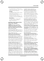
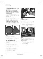
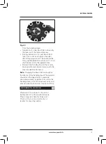
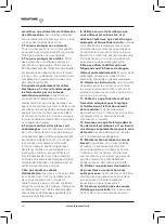
• The Sanding Head Drive Pin (
Fig. 11)
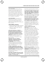
must locate and engage with the drive
arbor from the motor.
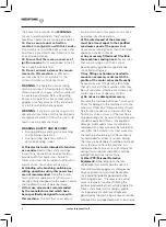
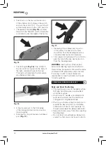
(Fig. 12)
• Gently press the Sanding Head onto the
motor coupling until it clicks into place.
Note
: Moving the Sanding Pad slightly
by hand may help correct location and
engagement of the drive pin and arbor.
• When the Sanding Head is successfully
located slide the Locking Lever fully to the
right and allow the bias spring to deploy
the Locking Pin into its service position.
To remove a Sanding Head:
• Pull out the Locking Pin and slide the
Locking Lever fully to the left.
• Gently ease the Sanding Head from the
machine.
Note:
The orientation of the Triangular
Sanding Head on its quick release
mechanism/coupling can be altered.
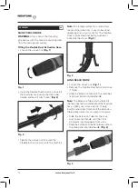
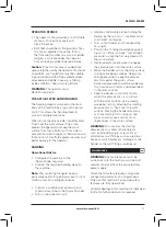
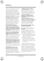
• Push down on the Locking Button
(Fig 13)
and turn the button to the unlocked position.
• Turn the Triangular Sanding Head on
its quick release mechanism to the
desired orientation.
• Relock the Sanding Head by returning the
Locking Button to the locked position.
Note:
Pictograms are provided on the casing
of the Sanding Head next to the Locking
Button to aid the operator.
Note:
Repositioning the Sanding Head
on its quick release mechanism/coupling
may allow the operator greater flexibility
in accessing awkward wall areas.
THE MACHINES CONTROLS
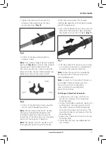
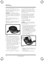
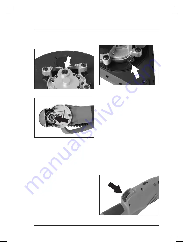
• The ‘ON/OFF’ slide switch
(Fig. 14)
is a
latching type. Slide it forward to start the
motor. Push forward and down on the
central section of the switch to latch it in
the ‘ON’ position
www.leroymerlin.fr
Fig. 11
Fig. 12
Fig. 13
Fig. 14
Содержание 72274475
Страница 21: ...www leroymerlin fr 21 PONCEUSE A BRAS TELESCOPIQUE POUR PLAQUE DE PLATRE...
Страница 44: ......


