Installation | 19
3.6 Mounting
WARNING
Use suitable Personal
Protective Equipment
when operating power tools.
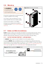
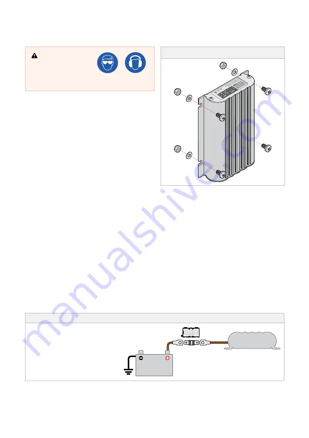
Figure 3.6.1:
Mounting the Charger
Ensure the mounting location is structural enough
to support the BCDC and its cabling.
Use 4 × M6 or similar sized fasteners to firmly
secure the BCDC Core in its mounting location.
Check the LED indicators on the Battery
Charger can be accessed and are visible for
troubleshooting (see
3.7 Cable and Wire Installations
NOTE:
Damage to cabling can cause failure of the BCDC and vehicle electrical systems. Ensure
cabling is clear of sharp edges or moving parts, and have enough slack to allow for flexing.
REDARC recommend using cable ties and conduit or split tubing to manage cabling.
3.7.1 OUTPUT AUXILIARY BATTERY — BROWN CABLE
The
BROWN
cable is used to connect the BCDC Core to the auxiliary battery.
Connect the
BROWN
cable to the MIDI fuse prior to connecting to the positive terminal of the
auxiliary battery. Ensure the cable length is at maximum 1m from the Battery Charger and the MIDI
fuse is mounted in close proximity of the auxiliary battery (see
"Figure 3.5.2: MIDI Style Bolt-Down
"Table 3.5.1: Fuse Rating" (page 18)
for appropriate size fuses.
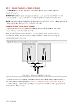
Figure 3.7.1.1:
Connecting the
BROWN
Cable
Auxiliary Battery Input
Connect the
BROWN
cable to the
positive terminal of the battery.
Auxiliary
Battery
Содержание BCDCN1225
Страница 34: ...34 NOTES ...
Страница 35: ...35 ...

