Installation | 23
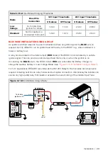
Table 3.7.5.2:
Input Mode Charging Thresholds
Mode
Blue Wire
Connection
12 V Input Thresholds
24 V Input Thresholds
ON above
OFF below
ON above
OFF below
Low
Voltage
D+ for Idle-Stop
'Ignition' for others
12.0 V
11.9 V
24.0 V
23.8 V
Standard
Not Connected, or
Connected to Ground
12.9 V
12.7 V
25.8 V
25.4 V
BLUE WIRE INSTALLATION USING A RELAY
An ignition switched relay can be used in situations where an ignition signal, the
BLUE
wire, is
required but it is difficult to run an ignition feed all the way to the BCDC (e.g. when installed in a
trailer or battery box).
A relay can be added on the Vehicle Input (
RED
cable) of the BCDC and controlled by a vehicle
ignition signal. This can provide a Vehicle Input feed that is only on when the ignition is on.
Connecting the
BLUE
wire to the BCDC Core's
RED
wire will enable the Battery Charger to
charge the auxiliary battery in 'Low Voltage Mode' (see
"Figure 3.7.5.3: Installation Using a Relay"
For 12 V applications, REDARC recommends the RK1260 Relay Kit that includes all components
required including heat shrink, relay holder and butt-splice connectors. Alternatively the installer can
source any high quality relay that meets or exceeds the current rating of the Vehicle Input Fuse.
Figure 3.7.5.3:
Installation Using a Relay
BR
OW
N
To Vehicle
Ignition or D+
Not
used
RK1260
BCDC
BLUE
Start
battery
Auxiliary
Battery
30
85
86
87
87A
RED
BLUE
RED
RED
Fuse
Fuse
ORANGE
Содержание BCDCN1225
Страница 34: ...34 NOTES ...
Страница 35: ...35 ...


