background image

20 | Installation

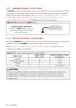
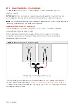
3.7.2  COMMON GROUND — BLACK CABLE 

The 

BLACK

 wire must be connected to a ground point that forms a common ground with both the 

start battery and the auxiliary battery. Most commonly the vehicle electrical systems ground/earth 
reference is the metal of the bodywork. See 

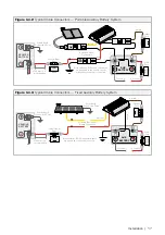
"Figure 3.4.2: Typical Cable Connectors — Portable 

Auxiliary Battery System" (page 17) 

and 

"Figure 3.4.3: Typical Cable Connectors — Fixed 

Auxiliary Battery System" (page 17)

 for illustrations of how this may be achieved. 

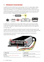
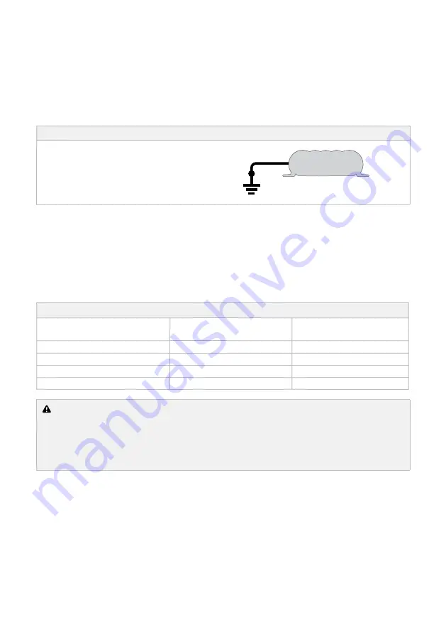
Figure 3.7.2.1: 

Connecting the 

BLACK

 cable

Common Ground Connection

Connect the 

BLACK

 wire to a ground  

point that is common with the start  

and auxiliary battery.

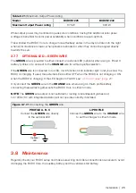
3.7.3  PROFILE SELECTION — ORANGE WIRE

Connect the 

ORANGE

 wire to set the maximum output voltage to suit your selected Charge Profile. 

If required to leave the 

ORANGE

 wire disconnected tape over the end of the wire. 

Refer to 

"Table 3.7.3.1: Charge Profile Selection for Cabin Installation"

 to select the correct  

profile for your installation configuration.

Table 3.7.3.1: 

Charge Profile Selection for Cabin Installation

Battery Type

Charge Profile  

(25°C / 75°F)

Maximum Battery Voltage 

Specification

AGM/Gel

14.6

Standard Lead Acid

B

15.0

Calcium

C

15.3

Lithium

Li

14.5 (LiFePO

4

)

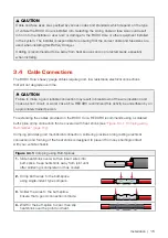
 CAUTION

Check the manufacturer’s data for your battery and ensure that the Maximum voltage of the 
Charging Profile you select does not exceed the manufacturer’s recommended maximum 
charging voltage. If the Maximum voltage is too high for your battery type, select another 
Charging Profile. 

Содержание BCDCN1225

Страница 1: ...BCDC Core Dual Input Multi Stage In Cabin Battery Charger MODELS BCDCN1225 25A CHARGER BCDCN1240 40A CHARGER ...

Страница 2: ... Designed around REDARCs tried and tested charging technology the Core25 and Core40 features a DC DC charger an MPPT solar regulator and a smart battery isolator all packed into one compact lightweight unit suitable for in cabin installations Using this proven combination the BCDC Core fully charges all common types of 12V automotive lead acid or LiFePO4 lithium auxiliary batteries while protectin...

Страница 3: ... 2 2 Battery Test Mode 10 2 3 Green Power Priority 10 3 INSTALLATION 11 3 1 Planning Installation 11 3 2 Installation Overview 12 3 3 Cable sizing 14 3 4 Cable Connections 15 3 5 Fusing 18 3 6 Mounting 19 3 7 Cable and Wire Installations 19 3 8 Maintenance 25 4 TROUBLESHOOTING 26 4 1 Error Codes 28 4 2 Turn On Off Thresholds 29 5 FREQUENTLY ASKED QUESTIONS 30 6 SPECIFICATIONS 32 WARRANTY 33 ...

Страница 4: ...ses during normal operation For this reason it is of utmost importance that you follow the instructions when installing and using the charger SAFETY MESSAGE CONVENTIONS Safety messages in this manual include a signal word to indicate the level of the hazard as follows WARNING Indicates a potentially hazardous situation which if not avoided could result in death or serious injury to the operator or...

Страница 5: ... recommended maximum charging current 6 When using the BCDC Core to charge a Lithium Iron Phosphate battery only batteries that feature an inbuilt battery management system featuring under and over voltage protection and cell balancing are suitable 7 The BCDC Core is not intended to supply power to a low voltage electrical system other than to charge a battery 8 Cable and fuse sizes are specified ...

Страница 6: ... voltage of either power source always outputting the ideal voltage to charge the selected battery type This capability makes it ideal for charging a wide variety of auxiliary 12V batteries including Lithium batteries and overcomes voltage drop over long cable runs In addition BCDC Core features an internal battery isolator that disconnects the auxiliary battery system from the start battery based...

Страница 7: ...nition Wire 479 mm 18 9 0 5 mm 20AWG Connects to ignition signal for vehicles with Smart Alternators Yellow Solar Input Cable 507 mm 20 8 mm 8AWG Connects to the solar panel input positive Green External LED Wire 484 mm 19 0 5 mm 20AWG Used to power optional LED connects to Orange Wire for Lithium batteries 1 2 Charge Profile LEDs The Dual Input In cabin BCDC Core features four different charging ...

Страница 8: ...e flashing refer to 4 1 Error Codes on page 28 1 3 2 STAGE LED The Stage LED indicates the Charge Profile Stage With any profile selected the charger will output a 3 Stage charging profile with Boost Absorption and Float Stages Table 1 3 2 1 Charge Stage LED Sequences outlines the LED sequences which indicate these stages and Figure 2 1 2 1 Charging Stages on page 9 explains the Charging Process T...

Страница 9: ...age maintains 13 3V 13 6V for LiFePO4 on the output battery keeping the battery topped up This counteracts the battery s self discharging or loads applied to the battery When the battery loses charge the Battery Charger will move back into the Boost stage Figure 2 1 2 1 Charging Stages Voltage Float Absorption Boost Current The BCDC has automatic timeouts to protect the battery from being damaged ...

Страница 10: ...iring in the event of damage to the output connection 2 3 Green Power Priority Green Power Priority is an automatic function that defines the order that input sources are prioritised This ensures that your battery will always take as much power as possible from solar panels before supplementing from other sources This lightens the load on your vehicle alternator and maximises the collection of fre...

Страница 11: ...timally below 55 C 130 F with good airflow At higher temperatures the unit will de rate output current up to 80 C 175 F at which point the unit will turn OFF IMPORTANT The BCDC Core must not be mounted in the engine bay of a vehicle Moisture ingress and heat build up may damage the Battery Charger START BATTERY The Battery Charger should be mounted as close as possible to the auxiliary battery wit...

Страница 12: ...lect GREEN ORANGE Connect all ground points to chassis earth Auxiliary Battery Fuse 1 B L A C K B R O W N Load Fuse Loads Low Voltage Disconnect optional 4 12 V or 24 V Start Battery Bank 12V Solar Panel Array Unregulated 3 Low Voltage Trigger Settings to D or Vehicle Ignition 2 YELLOW RED BLUE Fuse 1 Fuse Ratings to be as per the table in Table 3 5 1 Fuse Rating page 18 2 To connect the Blue wire...

Страница 13: ...es manufactured from 2015 onwards that are compliant with Euro 6 emissions regulations Determine if your vehicle has a smart alternator by checking for a battery sensor on your vehicles start battery as illustrated in Figure 3 2 2 1 Standard Alternator vs Variable Voltage Alternator page 13 Older vehicles or other models with fixed voltage or temperature compensating alternators do not require the...

Страница 14: ...ing The heavy gauge cables on BCDC Core 25 and Core 40 carry peak currents of up to 35 55A respectively To carry this current effectively the wire gauge required when extending this cables depends on the length of cable run required Refer to Table 3 3 1 Cable and Lug Sizing page 14 for cable thickness requirements for the following cables Brown Output Cable Red Vehicle Input Cable Black Ground Cab...

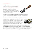
Страница 15: ...e wire insulation and cause a short circuit or worst case a fire REDARC recommend this activity be undertaken by an appropriately trained person For extending the cables provided on the BCDC Core REDARC recommends using a soldered butt splice crimp connection that is covered with heat shrink see Figure 3 4 1 Crimping using Butt Splices page 15 Crimping provides good mechanical connection soldering...

Страница 16: ... include 4 10mm 8B S crimp lugs that allow connection of the Vehicle Input and Output cables to the MIDI fuse holders in the kit For cables that require disconnection such as when using a portable battery box or portable solar panels Anderson SB50 connectors may be used These connectors are commonly used where the Battery Charger and auxiliary battery is mounted in a battery box or in a trailer wh...

Страница 17: ...s when Anderson plug is connected BROWN RED BLACK YELLOW 12 V Load Fuse To Loads To Loads VEHICLE BATTERY Figure 3 4 3 Typical Cable Connectors Fixed Auxiliary Battery System AUX BATTERY VEHICLE BATTERY Vehicle Input Fuse Output Fuse Vehicle Earth Connection Point Solar Earth Connection Point 100 mm 3 9 recommended Both batteries BCDC and solar panels are grounded to the vehicle chassis BROWN RED ...

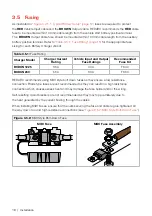
Страница 18: ...nt Rating Vehicle Input and Output Fuse Ratings Recommended Fuse Kit BCDCN1225 35A 40A FK40 BCDCN240 55A 60A FK60 REDARC recommends using MIDI style bolt down fuses as they ensure a low resistance connection Blade type fuses are not recommended as they can result in a high resistance connection which causes excess heat and may damage the fuse holder and or the wiring Self resetting circuit breaker...

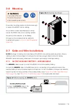
Страница 19: ...is clear of sharp edges or moving parts and have enough slack to allow for flexing REDARC recommend using cable ties and conduit or split tubing to manage cabling 3 7 1 OUTPUT AUXILIARY BATTERY BROWN CABLE The BROWN cable is used to connect the BCDC Core to the auxiliary battery Connect the BROWN cable to the MIDI fuse prior to connecting to the positive terminal of the auxiliary battery Ensure th...

Страница 20: ... 7 3 PROFILE SELECTION ORANGE WIRE Connect the ORANGE wire to set the maximum output voltage to suit your selected Charge Profile If required to leave the ORANGE wire disconnected tape over the end of the wire Refer to Table 3 7 3 1 Charge Profile Selection for Cabin Installation to select the correct profile for your installation configuration Table 3 7 3 1 Charge Profile Selection for Cabin Inst...

Страница 21: ...e charger to Lithium mode Start Battery 3 7 4 VEHICLE INPUT RED CABLE The RED cable is used to connect the BCDC to the vehicles start battery Connect the RED cable to the MIDI fuse prior to connecting to the positive terminal of the start battery Ensure the MIDI fuse is mounted within 100mm of cable length from the start battery see Figure 3 5 2 MIDI Style Bolt Down Fuse page 18 See Table 3 5 1 Fu...

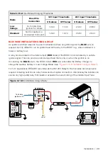
Страница 22: ...re to a signal which is active when the engine is running For most vehicles the Ignition ON signal is sufficient A suitable signal source is commonly found in the vehicle s engine bay or cabin fuse box For vehicles equipped with Idle Stop or Stop Start connect the BLUE wire to the D signal contact your vehicle dealer for details On vehicles operating with smart alternator or Idle Stop technology l...

Страница 23: ...put RED cable of the BCDC and controlled by a vehicle ignition signal This can provide a Vehicle Input feed that is only on when the ignition is on Connecting the BLUE wire to the BCDC Core s RED wire will enable the Battery Charger to charge the auxiliary battery in Low Voltage Mode see Figure 3 7 5 3 Installation Using a Relay For 12V applications REDARC recommends the RK1260 Relay Kit that incl...

Страница 24: ...o limitation on how many solar panels you can connect in parallel to your BCDC but you will need to size the cables correctly When connecting multiple 12V solar panels it is important to connect them in parallel Connecting in parallel ensures the output voltage remains the same while increasing the overall power output of the array Figure 3 7 6 1 Connecting solar panels in parallel Example only pa...

Страница 25: ... an LED it will function as an indicator light to let you know the BCDC is charging If used this external LED is either OFF when the BCDC is not charging or ON when the BCDC is charging If the LED begins to FLASH see 4 1 Error Codes page 28 Only connect the GREEN wire to the ORANGE wire when using a Lithium profile battery connecting these wires together sets the BCDC Core to Lithium mode NOTE The...

Страница 26: ...elow the turn on threshold see 4 2 Turn On Off Thresholds page 29 There is no connection to the auxiliary battery 1 Check that the Vehicle RED wire and or Solar YELLOW wire are electrically connected The Vehicle RED wire should connect directly to the Vehicle battery positive terminal via an adequately rated fuse The Solar YELLOW wire should connect directly to the Solar Panel positive terminal wi...

Страница 27: ...ists contact your local Auto Electrician The BCDC is connected to the Vehicle but the Vehicle LED is OFF This indicates that the required turn ON conditions for this source have not been met OR the Solar input is supplying the full input power requirements of the charger With the BLUE wire left unconnected the voltage at the RED wire must be above 12 9V for a 12V installation or above 25 8V for a ...

Страница 28: ... 3 5 second off Output Battery Fault Volts too high 5 flash followed by 3 5 second off Input under voltage Battery 3 6 flash followed by 3 5 second off Input over voltage Battery or Solar panel or the Solar Panel is connected in reverse polairty 3 If the unit is being supplied power from the vehicle and solar simultaneously and ONE of those sources is undervoltage that specific source LED will fla...

Страница 29: ...ing BELOW 12 2V 11 3V 24 4V 22 6V N A Turn OFF instantly BELOW 8 0V 8 0V 9 0V Turn OFF after 20 s BELOW 9 0V 9 0V N A Input Overvoltage shutdown Turn ON BELOW 15 5V 32 0V 32 0V Turn OFF instantly ABOVE 16 0V 32 5V 33 0V Turn OFF after 20 s ABOVE 15 6V 32 1V N A Output Undervoltage shutdown 1 Shutdown if Output Battery 0V 1Tested every 100 seconds 2 Tested constantly There is a maximum 20 second de...

Страница 30: ... output a REDARC proprietary charging algorithm independent of the input This allows the unit to charge specific to the battery type even if the input voltage is low due to voltage drop Where should I mount the BCDC Core Input Unit The BCDC Core Input should be mounted as close as possible to the battery being charged generally called the Auxiliary or House battery If the BCDC Core Input is to be ...

Страница 31: ...turned On I ve followed the trouble shooting guide and the setup is fine what s the problem The most likely cause of this issue is that the BCDC Core Input is somehow stuck in 24V mode Try disconnecting the Vehicle wire RED and the Output wire BROWN and then reconnecting it If the problem persists contact REDARC Can the BCDC Core Input charge from Solar and Vehicle power at the same time Yes The B...

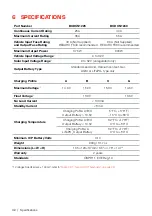
Страница 32: ...ium content Gel AGM or LiFePO4 type only Charging Profile A B C Li Maximum Voltage 1 14 6V 15 0V 15 3V 14 5V Float Voltage 1 13 3V 13 6V No Load Current 100mA Standby Current 8mA Charging Temperature Charging Pofile A B C Output Battery 10 5V 5 F to 176 F 15 C to 80 C Charging Pofile A B C Output Battery 10 5V 32 F to 176 F 0 C to 80 C Charging Pofile Li LiFePO4 Output Battery 32 F to 176 F 0 C to...

Страница 33: ...nc 308 Component Dr Smithfield NC 27577 USA Australia 61 8 8322 4848 New Zealand 64 9 222 1024 UK Europe 44 0 20 3930 8109 USA 1 704 247 5150 Canada 1 604 260 5512 Mexico 52 558 526 2898 CHECKING THE PRODUCT SERIAL NUMBER The Product Serial Number is located on the Main Unit and on the product packaging Design and specifications are subject to change without notice Copyright 2022 REDARC Electronic...

Страница 34: ...34 NOTES ...

Страница 35: ...35 ...

Страница 36: ... CONTACT Tech Support 1300 REDARC Head Office 61 8 8322 4848 New Zealand 64 9 222 1024 UK Europe 44 0 20 3930 8109 redarc com au USA 1 704 247 5150 Canada 1 604 260 5512 Mexico 52 558 526 2898 redarcelectronics com ...

Отзывы: