background image


Version 1.6.24 BETA


©2011 RED.COM INC. 

JULY 25, 2011 

166 

166 

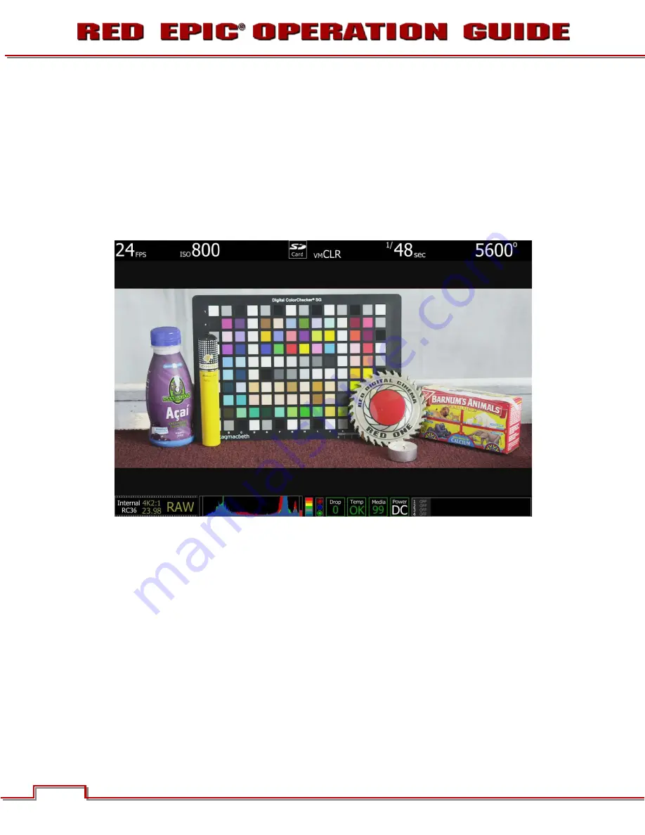
Select False Color – Video: note the √ V icon in the GUI when active. This mode allows us to check the 

RGB video levels of the scene. As the peak white chips on the test chart are showing up in green and 

the underexpose areas are showing up in dark blue, this says the monitor path video levels are only 

ranging between 44 IRE and 1 IRE.  
Because the scene is under exposed, when the recorded .R3D file is color corrected in post-production, 

the scene’s highlight information will certainly not be clipped, however the  shadow information will 

probably display with significant noise once pushed to an acceptable brightness. 

OVEREXPOSURE (~ 2 STOPS) 


ISO 800 - Monitor Output 

In the image above it is obvious  the camera is over exposed. The monitor is very bright and the 

histogram is justified to the right. Note the red bar at the right edge of the histogram and the vertical 

color stack to the right of the histogram is showing red plus the three traffic lights to the right of that are 

all illuminated. These indicators are suggesting that a signification portion of the sensor’s RAW data is 

“at clip”, and this clipping is occurring on Red, Green and Blue channels. 

Содержание EPIC MYSTERIUM-X

Страница 1: ......

Страница 2: ...THIS PAGE INTENTIONALLY BLANK...

Страница 3: ...ED EPIC 43 1 Attach Power Source 43 Battery 43 DC Power 44 2 Power UP 44 3 Preparing to Record 44 Connect and Format Media 45 Perform a Black Shading Calibration 46 Adjust Project Settings 46 4 Record...

Страница 4: ...tions 162 Reel No Slate Camera ID Camera Position 162 APPENDIX G EXPOSURE USING FALSE COLOR AND ISO 164 Underexposure 2 stops 164 Overexposure 2 stops 166 Appropriate Exposure 169 Adjusting the ISO Ra...

Страница 5: ...irect or indirect arising from the use of any technical or operational information contained in this document For comments or questions specifically about the Operations Guide content please send a de...

Страница 6: ...user is encouraged to try to correct the interference by one or more of the following measures 1 Reorient or relocate the receiving antenna 2 Increase the separation between the equipment and receive...

Страница 7: ...e equipment according to the instruction manual EUROPEAN UNION COMPLIANCE STATEMENTS RED declares that the equipment described in this document is in conformance with the requirements of the European...

Страница 8: ...ducts to your local retailer upon purchase of an equivalent new product Disposing of this product correctly will help save valuable resources and prevent any potential negative effects on human health...

Страница 9: ...l times E DO NOT attempt to modify dismantle or open your camera lens or other accessory as doing so may expose you to electric shock and serious injury There are no user serviceable parts inside Alte...

Страница 10: ...esult in overheating of the camera degraded operation and in extreme situations damage to the camera N DO NOT operate or store near any heat sources such as radiators heat registers stoves or any othe...

Страница 11: ...ntal regulations For example California law requires that all rechargeable batteries must be recycled by an authorized recycle center Storing batteries fully charged or in high temperature conditions...

Страница 12: ...ately equivalent to 16mm hence the maximum recording resolution with a B4 lens is 2K RAW 2048 x 1152 pixel progressive scan MYSTERIUM X SENSOR The MYSTERIUM X sensor has been specifically designed for...

Страница 13: ...ure is 1 48th sec the X track exposure will be 2 stops faster 1 192 sec The ISO and Aperture remain the same for both exposures During acquisition and recording the two tracks are motion conjoined mea...

Страница 14: ...RDING The RED EPIC can record up to two discreet channels of microphone level uncompressed 24 bit 48 KHz audio four channels of microphone level or line level audio inputs when equipped with a PRO I O...

Страница 15: ...support one VIEWFINDER output suitable for use by a BOMB EVF or RED LCD plus one HD SDI based PROGRAM output Each output can support a set of overlay graphics including camera GUI timecode clip name...

Страница 16: ...will not show the secondary menus only the main screen menus When an HD SDI monitor is connected WITHOUT an LCD or EVF and in PREVIEW mode the HD SDI monitor will display the menus as if it were the L...

Страница 17: ...r LCD displays camera parameters media and battery capacity and REDmote menus Figure 3 REDmote LCD display REDmote includes a rechargeable Li Ion battery which automatically re charges when attached t...

Страница 18: ...ording This includes camera specific setup information project and clip management information Clip Name Time Code Date and GMT lens and shutter speed angle parameters audio settings and any video ima...

Страница 19: ...r always updates at the same frame rate as the recording irrespective of whether the camera is operating in normal Vari Speed Time Lapse or Animation recording mode This ensures that a valid SMPTE tim...

Страница 20: ...atus LED Figure 4 Power Record Button Status LEDs Power Status LED Indicates Status of Power Power Available Not Available Power O K Power Record Button Powers camera Up Down and initiates Record Stop...

Страница 21: ...ined camera function Undefined by Default User Key 1 User Key 2 Press both keys to Eject unmount REDMAG 1 8 SSD Media Focus Record Button Touch for Auto Focus fully depress to Start or Stop Record Med...

Страница 22: ...s Side Handle battery door to permit battery exchange Focus Record Button Touch for Auto Focus fully depress to Start or Stop Record Adjustment Ring Selects and adjusts camera parameter values Similar...

Страница 23: ...011 RED COM INC 21 FRONT A Stills Movie Slider Figure 7 Side Handle Controls Front Stills Movie Slider Selects between STILLS and MOVIE modes of operation NOTE This switch is not active at this time D...

Страница 24: ...User Keys A D B Rocker Switch E System Keys 1 3 C Navigation Group F Thumbwheel Lock Figure 8 RED Side Handle Controls Rear Menu Button Press to access camera setup menus Rocker Switch Increases or d...

Страница 25: ...er Keys User Function Keys A D F The specific function of these keys may be programmed by the user Default settings for User Function Keys A D are as follow User Key A Press to execute user defined fu...

Страница 26: ...the camera if necessary 2 Remove the brain side plate if installed by removing the single screw located at the bottom 3 Rotate upwards to disengage lip at top of side plate from camera brain 4 Insert...

Страница 27: ...if necessary 2 Rotate the thumbscrew downwards until detached from camera body 3 Rotate upwards to disengage lip at top of side handle from camera brain 4 Remove side handle from camera Rotate thumbs...

Страница 28: ...4 8 B Release Button L G MENU Button L Power Lock Slider C Record LED H Soft Menu Keys 1 3 M Release Button L D Power LED I Navigation Group N USB Connector E Rocker Switch J Focus Record Button Still...

Страница 29: ...ion of camera parameter and adjustment of selected camera parameter Figure 11 Side Handle Navigation Group A Scroll Wheel B Direction Keys C Enter Button Scroll Wheel Selects and adjusts selected came...

Страница 30: ...gure 12 BOMB EVF A Focus Ring B C Brightness Control D EVF Tally Light Focus Ring Adjusts optimal subject focus for your eye Available diopter range is 2 0 to 5 0 EVF User Key B Increases EVF display...

Страница 31: ...M INC 29 RED LCD Figure 13 RED LCD A Backlight Adjust B Power Key C LCD User Key Backlight Adjust Adjusts LCD backlight intensity Power Key Not Used LCD User Key Press to execute user defined function...

Страница 32: ...C Press to execute user defined function Default Toggles False Color Exposure NOTE The touchscreen LCD also allows navigation of camera menus and selection and adjustment of camera parameters by dire...

Страница 33: ...CAMERA BRAIN THAT WILL NOT BE COVERED UNDER WARRANTY POWER SOURCES SIDE HANDLE The optional Side Handle accepts one 30Wh REDVOLT battery which can power the camera and typical accessories for approxi...

Страница 34: ...button The Power Status LED will initially go out and within 5 seconds illuminate Orange to confirm the camera is powering up then it will illuminate Green confirming the camera is powered up and rea...

Страница 35: ...camera is damaged by overheating the camera warranty will be voided Once the updated fan has been installed and the camera is powered up the message will continue to appear Press OK then go to SECONDA...

Страница 36: ...mount and lens are installed Shutter Speed Exposure Time or Degrees White Balance Color Temp Resolution Record Resolution Quality REDCODE setting Cursors Reference cursors Safe Action Safe Title Pict...

Страница 37: ...via Ethernet connection RIG Indicates 3D rig metadata is present Media Status Media location and remaining media capacity in Power Indicates D C supply voltage or of remaining battery capacity Includ...

Страница 38: ...parameter then press ENTER adjust with the Scroll Wheel and press ENTER a second time to confirm the value change In the above GUI example the Scroll Wheel has been used to move the red cursor to the...

Страница 39: ...EDVOLT battery in the Side Handle to power the camera power status displays the location of the power source example SH Side Handle and reports the of remaining battery capacity and the displayed text...

Страница 40: ...exposure level at risk of clipping and may not be recoverable by lowering ISO or FLUT values in post production SIDE HANDLE As you navigate and adjust settings on the camera main menu settings only th...

Страница 41: ...Time or Degrees White Balance Color Temp Resolution Record Resolution Quality REDCODE setting Clip Filename Filename of the clip that will be shot Project Frame Rate Current project TIME BASE Clip Met...

Страница 42: ...he Upper Status Row Moves Cursor to the Upper Status Row if the Cursor is positioned on Lower Status Row DOWN Selects Advanced Settings menu when Cursor is positioned on the Lower Status Row As an exa...

Страница 43: ...of the screen will bring up the Settings menu Refer to SECONDARY MENUS SETTINGS for complete information Touching Media Status indicator will bring up the Media menu Refer to SECONDARY MENUS MEDIA for...

Страница 44: ...3 The camera will immediately power down LOCK UNLOCK TOUCHSCREEN OPRERATION LOCK To lock out the touchscreen operation touch and hold the MENU icon until the LOCK icon displays indicating the touchscr...

Страница 45: ...IN power supply has priority and will power the camera instead of the battery BATTERY Connect a RED battery to the camera in one of the following ways SIDE HANDLE Attach a Side Handle and insert a RED...

Страница 46: ...EPIC AC Power Adapter is 150W 15V 10A The output of the adapter is over current protected and will shut down if an excess load condition occurs If the output trips for any reason remove any external l...

Страница 47: ...slightly from the SSD slot as indicated above When SSD media is inserted into the camera the camera will recognize if the media is unformatted On LCD EVF and external monitors in the media section of...

Страница 48: ...ENTER once more to confirm If using a Touch Screen select SECONDARY MENUS SETTINGS PROJECT TIME BASE Adjust by sliding your finger left right or tapping on the desired value and then press anywhere el...

Страница 49: ...using the Scroll Wheel and then press ENTER to confirm Available REDCODE compression options are RC 3 1 through RC 18 1 If using a Touch Screen press the QUALITY icon adjust the REDCODE value by slidi...

Страница 50: ...SSDs are very robust but should be treated with equal care as exposed film or a videotape master We recommend storing digital media that contains your footage in a secure location and backing up the d...

Страница 51: ...nu the GPO trigger output in the CNTL connector will pulse 5 PLAYBACK Playback of recorded clips is not currently enabled in camera firmware and must be performed off the camera Off load the Clips fro...

Страница 52: ...not recommended the Side Handle can be used stand alone to make basic adjustments to FPS ISO Shutter Speed Resolution and REDcode located on the Main Menu screen Use the Navigation Group to make thes...

Страница 53: ...nd press ENTER 3 Use the Scroll Wheel to adjust the selected parameter value 4 When desired selection is made press the MENU button to set TOUCHSCREEN 1 Press and hold the desired parameter to gain ac...

Страница 54: ...HD 1 sec 96 fps 5K ANA 1 sec 120 fps 5K 2 4 1 1 sec 96 fps 5K FF 1 sec 96 fps 5K 2 1 Default is 24 fps or the selected Project TIME BASE frame rate if not 23 98 or 24 00 fps 1 sec translates to 1 sec...

Страница 55: ...rovides quick selection of the most common Varispeed frame rates ADVANCED SETTINGS When selected a numerical keypad will appear allowing the desired Varispeed Framerate to be entered in 1 fps incremen...

Страница 56: ...POSURE BASIC SETTINGS Adjusts the exposure of each frame captured by the MYSTERIUM X sensor Shutter speed presets are provided for all common speeds and shutter angles for 24 25 fps and 50 60 fps proj...

Страница 57: ...value and permits entry in any of the three following common units EXPOSURE Shutter Speed INTEGRATION TIME or ABSOLUTE ANGLE Shutter Angle EXPOSURE SPEED Provides the ability to enter the Exposure va...

Страница 58: ...to 1 000 mS milliseconds Default is 20 833 MS ABSOLUTE ANGLE Provides the ability to enter the Exposure value as a Shutter Angle xx Degrees Range is 4 0 to 360 0 Degrees Default is 180 0 Degrees As yo...

Страница 59: ...192 45 1 50 172 8 1 348 22 5 1 60 144 1 696 11 1 96 90 1 1000 8 6 Equivalent Shutter 1 Frame Rate x 360 Angle E g 1 24 x 360 180 1 8640 180 1 48 DEGREES SHUTTER DEGREES SHUTTER 270 1 32 72 1 120 180...

Страница 60: ...set to 9 000K CLOUDY Preset to 7 500K DAYLIGHT Preset to 5 600K FLASH Preset to 5 500K FLOURESCENT Preset to 4 500K TUNGSTEN Preset to 3 200K INCANDECENT Preset to 2 800K COLOR TEMP Allows you to manu...

Страница 61: ...esets Tint will be reset to zero which is the default value CALC WHITE BALANCE The Calc White Balance function analyzes the central 25 of the image visible in the monitor to calculate a Color Temperat...

Страница 62: ...72 75 90 96 100 120 150 175 210 250 288 300 5K FF RC 3 1 RC 4 1 RC 4 1 RC 6 1 RC 7 1 RC 8 1 RC 9 1 RC 10 1 RC 12 1 RC 12 1 5K 2 1 RC 3 1 RC 3 1 RC 4 1 RC 6 1 RC 6 1 RC 8 1 RC 9 1 RC 9 1 RC 11 1 RC 12...

Страница 63: ...mplemented at this time HDR MENU Available options are HDR OFF HDRx and STOPS HDR ON OFF By default HDRx is OFF HDR button is illuminated Blue In the Lower Status Group of the Viewfinder screen the HD...

Страница 64: ...MENU The Focus Menu is used to enable and select Auto Focus parameters including MODE and ZONES MODE To adjust the MODE parameter select the Menu box and use the UP DOWN arrows to adjust Available opt...

Страница 65: ...are in focus the circle will be Yellow or Green When objects located in the circle are out of focus the circle will be Red SPOT Provides a small round target for precise focus similar to Center focus...

Страница 66: ...crease the size 3 times After that when you double tap the spot focus circle it will decrease in size MATRIX Provides many targets for focus When many objects on the screen are in focus many boxes wil...

Страница 67: ...accessible by using the arrow keys in the Preset name field CREATE PRESET NOTE A properly formatted REDMAG 1 8 SSD must be installed on the camera as this is where presets are stored When selected all...

Страница 68: ...and Enter button enter the desired name When finished press the Menu button to close the keyboard PRESET INFORMATION Use the arrow keys and Enter button to select the information you want to be store...

Страница 69: ...e external memory 1 8 SSD to the camera or apply available RMD presets NOTE Exported presets will be located in a folder labeled Presets on the CF or 1 8 SSD This is also the location to place any pre...

Страница 70: ...ected or no presets are saved to the media this selection will remain Grayed out until a preset is exported of course You will then be asked if you want to apply the imported preset If No is selected...

Страница 71: ...ernal media 1 8 SSD IMPORTANT You will not be warned of the deletion nor asked to confirm this deletion Be sure to save your preset to the external media 1 8 SSD for later use before deleting the pres...

Страница 72: ...MEDIA and EJECT MEDIA IMPORTANT Media MUST be ejected from the camera before removal to prevent corruption and or loss of data on media SELECT MEDIA Allows you to select the Media location to be used...

Страница 73: ...ith a letter A through Z Default is A CAMERA POS POSITION Identifies the camera position as Right Left or Center Default is Center FORMAT MEDIA When selected a new dialog box will appear allowing you...

Страница 74: ...hrough Z Default is A CAMERA POS POSITION Identifies the camera position as Right Left or Center Default is Center FORMAT When selected formats the media and adds the selected properties During format...

Страница 75: ...essfully SETTINGS MENU This section describes the various secondary controls available to configure the camera Menu options are DISPLAY LOOK SENSOR PROJECT MODES AUDIO VIDEO SETUP and MAINTENANCE DISP...

Страница 76: ...cted the icon E will be displayed in the Lower Status Group The EXPOSURE meter s color bands provide the following information PURPLE Minimum Exposure RED Maximum Exposure Between minimum and maximum...

Страница 77: ...he icon V will be displayedin the Lower Status Group Purple represents Super Black Dark Blue represents Black Teal represents 3 stops under 18 Gray Green represents 18 Gray Pink represents Skin Tone S...

Страница 78: ...he luminance value of the ISO adjusted image FOCUS FOCUS displays a Red color overlay that outlines the edges of objects that are in sharp focus By adjusting your lens zoom and focus you can see which...

Страница 79: ...he sensor in 1 1 pixel resolution When enabled the 1 1 text in the Lower Status Group will change to Green If in Magnify mode when the Record button is pressed the system will automatically exit this...

Страница 80: ...er for mid tone or shadows By default Zebra 1 and 2 are disabled ZEBRA 1 To enable select ZEBRA 1 check box Areas of the image exposed within these ranges will be indicated by crosshatched overlays at...

Страница 81: ...e below High IRE Change the desired setting between 1 and 99 default is 1 Low IRE Change the desired setting between 0 and 84 default is 48 OVERLAY Allows you to enable and color code graphic overlays...

Страница 82: ...0 25 50 75 and 100 Color The color setting for AF Zones AE Zone Faces Center Grid and Look Around may be adjusted Options are White Blue Yellow Green Red or Black Select the color that provides maxim...

Страница 83: ...lay of Shutter Exposure on Main screen as Time 1 xx sec or Angle Degrees APERTURE Selects GUI display of f stop as 1 4 f Stop or 1 3 f Stop TIME CODE Selects GUI display of Timecode as Time of Day TOD...

Страница 84: ...in Red text over a Gray background for nighttime shooting conditions FRAME GUIDE This sub menu provides a selection of frame guides and safe action and safe title guides User definable safe action and...

Страница 85: ...Available options are Off Full 4 3 16 9 1 85 1 1 9 1 2 4 1 or User Full is displayed by default and illustrated below User Frame guides can be set to your own preferences through the User Settings Ava...

Страница 86: ...e color to White Blue Yellow Green Red or Black Select the color that provides maximum color contrast with the scene you are shooting TRANSPARANCY Sets the frame guide transparency Available options a...

Страница 87: ...T RATIO For both Title Guide and Action Guide available options are OFF 16 9 14 9 4 3 2 4 1 1 85 1 and User Default is OFF User Title Guide and Action Guide can be set to your own preferences through...

Страница 88: ...Sets Title Guide and Action Guide line color to White Blue Yellow Green Red or Black Select the color that provides maximum color contrast with the scene you are shooting TRANSPARENCY Sets Title Guide...

Страница 89: ...lide to the right for a brighter display slide to the left for a dimmer display TOUCH GESTURES These options apply ONLY to the Touchscreen LCD Pinch to Magnify When selected allows you to use two fing...

Страница 90: ...actual REDCODE RAW data being recorded COLOR The Color sub menu permits adjustment of SATURATION CONTRAST and BRIGHTNESS SATURATION Adjusts color saturation Range is 0 0 monochrome to 2 0 super color...

Страница 91: ...n of the BLUE channel only Range is 0 0 no Blue to 4 0 Default is 1 0 GREEN Adjusts the gain of the GREEN channel only Range is 0 0 no Green to 4 0 Default is 1 0 FLUT The FLUT sub menu permits adjust...

Страница 92: ...Blacks CURVE The CURVE sub menu permits adjustment of the monitor output Color Space and Gamma curve Available options are REDGamma2 and REDLogFilm SENSOR Defines operational modes for the SENSOR Ava...

Страница 93: ...ming scan start to be synced to an external signal MODE Available options are OFF GENLOCK SHUTTER INTERNAL PROXY and SLAVE Default is Off OFF Shutter start time is defined by internal camera timing GE...

Страница 94: ...Options available are TIME BASE and TIME CODE TIME BASE Sets the TIME BASE fps to be used for the project the primary acquisition frame rate time code count and playback editing frame rate Setting is...

Страница 95: ...izes its internal timecode counter to that value at the beginning of each recording INT USER PROVIDED TC Available options are USE RTC TIME and SET MANUALLY The three 3 numerical boxes below allow you...

Страница 96: ...Allows you to enable disable and adjust levels for audio inputs Channel 1 4 Available options for each input are OFF and UNB Unbalanced Default is OFF Audio channel level input are displayed in the l...

Страница 97: ...is plugged in the circle will remain Gray but the box around the signal will be highlighted jack is detected by the camera AUDIO OUTPUT Allows adjustment of audio output levels fed to the Headphone ja...

Страница 98: ...ogram is selected the HD SDI output provides a clean feed video with no graphic overlays TEST SIGNALS Permits the video monitor outputs to be replaced with a video test pattern Available test patterns...

Страница 99: ...is menu to select and program the camera user keys buttons NOTE To reset keys to default settings go to RESTORE A reboot of the camera is necessary to restore defaults NOTE Multiple keys can be progra...

Страница 100: ...Set focus mode for still Side Handle Movie Select Set focus mode for movie Side Handle Record Half Button Down HALF Press Request Side Handle Record Full Button Down Toggle Record Side Handle Tele Le...

Страница 101: ...Open Shutter Speed List REDmote Function 3 Key Down Open Color Temp List REDmote Record Half Button Down HALF Press Request REDmote Record Full Button Down Toggle Record REDmote Tele Level 1 Zoom In...

Страница 102: ...re Check Toggle REDCode Zoom Stop Zoom In Speed 1 Zoom In Speed 2 Zoom In Speed 3 Zoom In Speed 4 Zoom Out Speed 1 Zoom Out Speed 2 Zoom Out Speed 3 Zoom Out Speed 4 Brain LCD Br Up Brain LCD Br Down...

Страница 103: ...SSD media NOTE Enter time in 24 hour clock format i e 2 35 pm should be entered as 14 35 00 NETWORK Network Menu allows you to set an IP ADDRESS NETMASK GATEWAY and ENABLE DHCP IP ADDRESS Permits the...

Страница 104: ...ir the camera to a REDmote for wireless operation For paring procedures go to APPENDIX E REDMOTE OPERATION OPERATION WIRELESS CONNECTION This function also allows you to identify the camera CAMERA ID...

Страница 105: ...NABLE PASSTHROUGH Not implemented at this time WIRELESS DEVICES FOUND Displays discovered REDmotes in the drop down menu and allows pairing for wireless communication For details go to APPENDIX E REDM...

Страница 106: ...y on each camera boot Default is channel 15 GPIO GPIO selects the GPIO preferences sub menu CAMERA INPUT Permits the function of the SYNC IN GPI pin in the SYNC connector to be defined as Sync In Acce...

Страница 107: ...FAN CONTROL RECORD SPEED and STANDBY SPEED BEEP SPEAKER and EVF TALLY LIGHT FAN CONTROL Specifies cooling fan operation Available options are AUTO and MANUAL The default setting is AUTO Auto This sett...

Страница 108: ...FF and RECORD STOP When RECORD STOP is selected an audible beep will be heard when record is started and another when record is stopped EVF Tally Light When checked enables the Record Tally Red LED on...

Страница 109: ...ed the Viewfinder output s will display the camera Model current firmware Version installed and camera P I N SAVE LOG Select to write camera s LOG file to the REDMAG 1 8 SSD The LOG file is a diagnost...

Страница 110: ...iates a camera software firmware update If a software update is on the attached media you will be given the option to upgrade the camera earlier firmware version shown for reference ONLY For complete...

Страница 111: ...ensor is NOT exposed to the calibration light source by installing the lens cap properly 2 Ensure a properly formatted SSD is attached to the camera and properly formatted 3 Select OK to perform the B...

Страница 112: ...l be displayed Select OK to complete Black Shading calibration SELF TEST When selected allows you to perform a self test for the sensor and LCD Touchscreen ENABLE DISABLE SENSOR TEST PATTERN When sele...

Страница 113: ...EST PATTERN TOUCHSCREEN When selected allows you to perform a touchscreen self test When the touchscreen self test is on you can verify all areas of the touch screen respond to touch Simply touch each...

Страница 114: ...fter settings are restored DEFAULT SETTINGS RESTORED INITIALIZING RESTART Camera will automatically power down and will require you to manually power it up NOTE User key settings will be reset as well...

Страница 115: ...o prevent accidental powering down of the camera For details on the different ways to properly power down your RED EPIC refer to BASIC OPERATION POWER DOWN 1 Enter the Secondary Menu using the touch s...

Страница 116: ...software VERIFY CURRENT CAMERA FIRMWARE With the camera ON select SECONDARY MENUS SETTINGS MAINTENANCE SYSTEM INFO The camera s P I N number and current firmware version will be displayed UPGRADE PROC...

Страница 117: ...IC to v1 6 20 or higher series firmware you receive a New fan available please contact RED notification on the camera please contact RED technical support for assistance Press OK to use your camera as...

Страница 118: ...presets or log files you want to keep to your computer to prevent unwanted loss of your files Refer to APPENDIX B MANAGING DIGITAL MEDIA COPYING MEDIA MULTIPLE CAMERAS If multiple cameras are to be up...

Страница 119: ...001_0512A6 RDM Clips recorded to the media follow similar naming conventions A001_C001_0512A6_001 RDC and A001_C001_0512A6_H mov etc IMPORTANT Media must always be un mounted prior to removal or disco...

Страница 120: ...ty the media status will turn yellow at 5 it will turn red At 2 remaining the camera will cease recording This reserves a small amount of capacity for ancillary data to be written to the media NOTE Wh...

Страница 121: ...warned NOTE The camera will respond to physical removal of the media without un mounting and display MEDIA REMOVED PRIOR TO UNMOUNT DATA INTEGRITY RISK USING REDMOTE TOUCHSCREEN LCD 1 Go to SECONDARY...

Страница 122: ...edia and metadata files You will not need to copy the log magazine profile or presets files but if you do so it will do no harm ERASING MEDIA MACINTOSH OS X 1 Connect the REDMAG 1 8 SSD via RED STATIO...

Страница 123: ...t EXPLORE 3 Double click on the drive you wish to erase files from 4 Select all the files on the drive you wish to erase IMPORTANT Before performing the next step double check that this is the correct...

Страница 124: ...If single LED blinks or no LEDs illuminate when pressed battery requires charging BATTERY PERFORMANCE When fully charged to 16 4V 0 2V the REDVOLT battery is designed to provide approximately 30 45 mi...

Страница 125: ...ttery can also be partially charged to approximately 80 capacity in approximately 60 minutes RED Travelcharger with REDvolt Installed OPERATION INDICATOR Red Solid Charger ON no battery connected Yell...

Страница 126: ...o the charger s AC input and then into the AC power source 2 Verify that the charger s LED status bar is solid Red indicating ready to receive battery for charging 3 Insert a REDVOLT battery into the...

Страница 127: ...Version 1 6 24 BETA JULY 25 2011 2011 RED COM INC 125 APPENDIX D INPUT OUTPUT CONNECTORS BRAIN FRONT A MIC 1 3 5mm Audio Jack B MIC 2 3 5mm Audio Jack Figure18 Brain Connectors Front B A...

Страница 128: ...amera ground Microphone Level analog audio input signals are routed via a high quality A D and pre amplifier whose Gain may be controlled using the Input Level control to achieve the desired audio ref...

Страница 129: ...1 6 24 BETA JULY 25 2011 2011 RED COM INC 127 BRAIN REAR A HD SDI B Headphone C SYNC Video Sync D CTRL RS232 Control E GIG E Ethernet F DC IN Power Input G HDMI Figure 20 Brain Connectors Rear A B C...

Страница 130: ...29 97 Hz when in 1 5GHz HD SDI mode and 50 00 or 59 94 Hz when in 3GHz HD SDI mode The HD SDI output may be specified as a PROGRAM output clean feed video or as a PREVIEW output with SurroundView look...

Страница 131: ...RING RIGHT Right channel audio Out C SLEEVE GND Camera ground The camera s four audio channels may be monitored in pairs either 1L 2R or 3L 4 R or as a quad mix of 1 3L 2 4R based on the MIX parameter...

Страница 132: ...t Stop A SMPTE timecode input signal provides a frame accurate time stamp for each frame of recorded video A Video Genlock input signal may be used as a vertical interval reference signal for applicat...

Страница 133: ...3 3V Stop Record 3 3V Ground Transition During Stop Hold at Ground NOTE A pre fabricated SYNC interface cable is available from RED Digital Cinema Part No 790 0154 Video Sync Camera to 3 BNC 3 ft 1m W...

Страница 134: ...camera Alternatively this output pin may be used as a GPO General Purpose Output tally whose function is programmed in the USER KEYS menu Default is Record Tally Figure 23 View into camera CTRL RS232...

Страница 135: ...4 View into Ethernet Interface connector Mating connector FGG 0B 309 CLAD32Z PIN SIGNAL DESCRIPTION DIRECTION 1 B1_DC Data Pair C 2 B1_DC Data Pair C 3 B1_DD Data Pair D 4 B1_DD Data Pair D 5 B1_DA Da...

Страница 136: ...1 VBATT Power input 11 5 to 17VDC 2 3 SCL BATT Serial Battery Bus Clock 4 GROUND Power Return Camera Ground 5 6 SCA BATT Serial Battery Bus Data WARNING It is very important that both pairs of VBATT...

Страница 137: ...specified as a PROGRAM output clean feed video or as a PREVIEW output with SurroundView look around Clip Name Timecode and Safe Action Safe Title frame guides In addition to video data the HDMI output...

Страница 138: ...Module and or the camera Brain may occur The VIEWFINDER output Module to the front face of the Side SSD provides digital video communications and power interconnection between the camera and a RED EV...

Страница 139: ...re 27 REDmote Connections The Mini USB connector A may be used to charge the REDmote from a 3rd party USB power source The REDmote interface connector B allows communication between the REDmote and EP...

Страница 140: ...Switch F User Function Keys A D K Soft Menu Buttons 4 8 B Release Button L G MENU Button L Power Lock Switch C Record Status LED H Soft Menu Buttons 1 3 M Release Button R D Power Status LED I Navigat...

Страница 141: ...button to stop recording Off when camera is not ready to record ZOOM ROCKER SWITCH The pressure sensitive ZOOM rocker switch E may be assigned by the operator to one of a number of operational control...

Страница 142: ...ion refer to OPERATION REDMOTE MENUS SOFT MENU BUTTONS 1 3 NAVIGATION GROUP The Navigation Group I allows navigation through allowing navigation of camera menus and adjustment of selected parameters F...

Страница 143: ...g camera settings For complete information refer to OPERATION REDMOTE MENUS SOFT MENU BUTTONS 4 8 POWER LOCK SWITCH Below the ambient light sensor is the Power Lock switch T Sliding and holding in the...

Страница 144: ...t the REDmote into search mode The REDmote will ping for cameras it has been paired to When a paired camera or cameras is are found the available cameras will be displayed on the screen Select the des...

Страница 145: ...ile in the REDmote is IDLE Customizing Available Adjustment Parameters Local also gives you the options to setup what parameters you would like to be able to adjust directly using the REDmote You can...

Страница 146: ...to the desired location to place the parameter 5 Press Soft Menu Button 3 Setup The Setup window will appear on screen 6 Select Setup Slot 7 A new Setup window will appear displaying available parame...

Страница 147: ...tting parameters of the REDmote In particular F indicates the current firmware build of the REDmote Auto Shutdown When set will shut the REDmote down in the specified amount of time when the REDmote i...

Страница 148: ...ted to computer using USB cable the indicator will flash Green to indicate the battery is charging BATTERY LIFE Battery life is shown by a Green indicator at the lower Right corner of the screen same...

Страница 149: ...cted and controlling a camera wirelessly 1 Connect the USB connector to any computer computer must be ON to charge REDmote 2 Connect the Mini USB end to the REDmote USB Port located on the lower right...

Страница 150: ...ote over the male V Mount of the camera module 2 Press down until a click is heard which indicated the REDmote is securely attached 3 The REDmote will confirm by displaying DOCKED momentarily if REDmo...

Страница 151: ...iously WIRELESS CONNECTION PAIR CAMERA WITH REDMOTE When the REDmote is wirelessly connected to the camera the camera ID will be stored in the REDmote until the REDmote firmware is upgraded After sett...

Страница 152: ...and press the Enter button NOTE If wireless needed to be turned on you will need to press Soft Menu Button 3 again to get back into Setup options 5 Select Setup System to display the Setup System scr...

Страница 153: ...dd Wireless Device on the camera NOTE If after upgrading your EPIC to v1 6 xx and upgrading your REDmote to v771 your REDmote will not wirelessly connect to your EPIC and REDLINK upgrade required plea...

Страница 154: ...Soft Menu Button 1 under CONNECT 2 REDmote will display the name NA in this case and MAC address in parenthesis of the camera This can take 20 30 seconds NOTE If more than one camera has been PAIRED...

Страница 155: ...pts to connect with the camera after losing the cameras wireless signal until the REDmote is turned off or the camera is turned back on and REDmote automatically connects If Soft Menu Button 1 under C...

Страница 156: ...tus The wireless connection will be shown in the lower Right corner of the REDmote screen POWER UP DOWN Located on the upper right side of the REDmote is the Power Lock Switch refer to CONTROLS POWER...

Страница 157: ...lect the desired power down function ACCESSING CAMERA CONTROLS SETTINGS The Navigation Group is used to navigate through the camera s menus Refer to CAMERA OPERATIONAL CONTROLS REDMOTE NAVIGATION GROU...

Страница 158: ...return to the main screen Press the MENU button until the main screen is displayed USING REDMOTE LCD STAND ALONE The LOCAL function of the REDmote allows you to control the camera settings directly on...

Страница 159: ...USB to mini USB cable between the computer and the USB connector on the REDmote 2 Go to System Preferences and choose Network This may open automatically when the REDmote is connected 3 Look for a dev...

Страница 160: ...nformation will guide you through proper updating of your REDmote firmware MAC 1 Download the zip file to your desktop 2 Double click the zip file to uncompress 3 Open the newly created folder 4 Doubl...

Страница 161: ...n REDmote has been established Connection to REDMOTE has been achieved will be displayed 6 Click Select File and navigate to the redmote 1 bin file located in the same folder as REDmoteUpgradeApp 7 Se...

Страница 162: ...eral minutes Do not power down during this process as well as a Green status bar showing upgrade progress in percent 10 Once the File Transfer Status is completed the REDmote Software Wizard will disp...

Страница 163: ...OPERATING MULTIPLE CAMERAS USING A SINGLE REDMOTE To operate multiple cameras using a single REDmote first the REDmote must be paired to multiple cameras Refer to OPERATION WIRELESS CONNECTION for pai...

Страница 164: ...or RIGHT to identify the left eye and right eye camera in the stereo pair The Reel No Cam ID and Cam Pos can be set when formatting the media or after formatting by using the SET option Refer to SECO...

Страница 165: ...e same CAM ID the first clip recorded on each camera will have the same general file structure with the exception of the two wildcard characters which provide full protection against file name duplica...

Страница 166: ...to avoid clipping any highlights and also avoiding underexpose of elements in deep shadow which may therefore be prone to noise when developed in post production The following reference scene include...

Страница 167: ...Color Exposure note the E icon in the GUI when active This mode allows us to visualize where in the image underexposure is taking place These areas are indicated in purple It is clear those areas are...

Страница 168: ...highlight information will certainly not be clipped however the shadow information will probably display with significant noise once pushed to an acceptable brightness OVEREXPOSURE 2 STOPS ISO 800 Mon...

Страница 169: ...ect False Color Exposure note the E icon in the GUI when active This mode allows us to visualize where in the image over exposure is taking place These areas are indicated in red It is clear those are...

Страница 170: ...white chips on the test chart are Yellow this suggests that a significant portion of the monitor path video is at the maximum legal 100 IRE value Because the scene is over exposed when the recorded R3...

Страница 171: ...read evenly given that there are bright highlights on the coin we wish not to blow out Note that there is no red bar on either the left or the right edges of the histogram and the vertical color stack...

Страница 172: ...in the GUI when active This mode allows us to visualize where there is under exposure purple or over exposure red in the image In this case there is a very small area of purple under the cracker box...

Страница 173: ...rt and green in the background indicate that the scene s mid grey and skin tone elements plus peak white and blacks are all at appropriate levels Because the scene was well exposed when the recorded c...

Страница 174: ...rating have had the ISO rating adjusted first to ISO 6400 and then to ISO 100 NOTE Although the image and Histogram both adjust to changes in the ISO rating the sensor RAW meters do not change they al...

Страница 175: ...he iris to reduce the brightness of the first image you will be reducing exposure at the sensor this biases exposure in favor of protecting the scene highlight Alternatively if you choose to open the...

Страница 176: ...opped resized or repositioned These functions lessen the amount of time required for color correction or re framing of shots after the final cut has been completed REDCINE X can also encode 4K or 2K R...

Страница 177: ...t either a single clip or a sequence of clips as 4K or 2K resolution 10 bit DPX or 16 bit TIFF files REDCINE X can also render clips into standalone QuickTime movies using specific HD video codecs As...

Страница 178: ...ctronic circuitry CAMERA AND ACCESSORY EXTERIOR SURFACES Clean ONLY using a dry cloth When cleaning your camera and accessories remember that it is not waterproof and moisture can damage electronic ci...

Страница 179: ...ution onto the pad and not directly onto the lens surface SIDE HANDLE LCD Use Pancro Professional Lens Cleaner Part No PANCROCLN and Photographic Solutions Pac Pads Part No 05011 or equivalent to clea...

Страница 180: ...lled on RED EPIC Camera 3 Power up the camera 4 Power up RED Focus Refer to POWER UP DOWN NOTE Remember that RED Focus will AUTOMATICALLY power down after 3 minutes Press the Red button on the front t...

Страница 181: ...ly rotate the back focus adjustment screw to achieve optimum focus Turning CLOCKWISE moves the sensor forward Turning COUNTER CLOCKWISE moves the sensor rearward NOTE The center of the image will neve...

Страница 182: ...DOWN Displayed if media removed while recording DO NOT remove media while camera is recording Power down the camera verify the media is inserted properly inspect connectors for damage power up and res...

Страница 183: ...nd send to RED Technical Support to diagnose and confirm next steps NEW FAN AVAILABLE If after upgrading your EPIC to v1 6 20 or higher series firmware you receive a New fan available please contact R...

Страница 184: ...encoder 2K DPX TIFF OpenEXR RED RAY via optional encoder 1080p RGB or 4 2 2 720p 4 2 2 Quicktime JPEG Avid AAF MXF 1080p 4 2 0 720p 4 2 0 H 264 MP4 PROGRAM OUTPUT HD SDI Clean Feed 2K RGB 1080p RGB o...

Страница 185: ...Version 1 6 24 BETA JULY 25 2011 2011 RED COM INC 183 BRAIN DIMENSIONS FRONT VIEW...

Страница 186: ...Version 1 6 24 BETA 2011 RED COM INC JULY 25 2011 184 184 SIDE VIEW...

Страница 187: ...Version 1 6 24 BETA JULY 25 2011 2011 RED COM INC 185 TOP VIEW...

Страница 188: ...MENUSPRESS MENU ICON LCD OR MENU BUTTON TO ACCESS FOCUS EXPOSURE PRESETS POWER HDR MEDIA SETTTINGS SHUTDOWN POWERS DOWN CAMERA OFF HDRx OFF HDRx HDRx ON PRESETS USER DEFINED PRESETS CREATE IMPORT EXP...

Страница 189: ...OUTDOOR NIGHT Normal EXPOSURE TIME ANGLE Time APERTURE 1 4 F 1 3 F 1 3 F SIZE OFF FULL 2 4 1 Full TRANSPARENCY 0 25 50 75 100 50 1 9 1 USER 1 85 1 16 9 4 3 COLOR WHITE GRAY TEAL White BLUE RED BLACK...

Страница 190: ...IME BASE TIME CODE 0 TO 23 0 MINUTES 0 TO 59 0 SECONDS 0 TO 59 0 HOURS USER TC SECONDARY MENUSPRESS MENU ICON LCD OR MENU BUTTON TO ACCESS GO TO SHEET 1 OF 4 47 96 48 00 50 00 59 94 KEYS DATE TIME NET...

Страница 191: ...G SW UPDATE CALIBRATION SELF TEST RESTORE SYS DISPLAYS CAMERA PIN SOFTWARE VERSION SAVES SYSTEM LOG FILE TO EXTERNAL MEDIA CHECKS EXTERNAL MEDIA FOR SOFTWARE UPDATE PROMPTS FOR INSTALL BLACK SHADING 2...

Страница 192: ......

Отзывы: