


RealMan (Beijing) Intelligent Technology Co., Ltd.
71
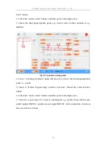
it in the table and click the “Delete” button. After the deletion, the robot works in the
Base coordinate system. Note that the Base coordinate system cannot be deleted.
2. Automatic Calibration
After selecting this feature, the current operation coordinate system can be calibrated
by the three-point method. First, fill in the name of the coordinate system (English
characters, no more than 10 characters). The tool end with a fixed pose is to contact the
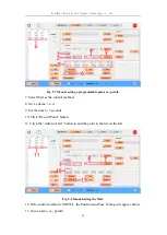
origin of the operation coordinate system, any point on the x axis (better if the distance
from the origin is greater than 10cm) and any point on the y axis (better if the distance
from the origin is greater than 10cm), respectively. After the calibration of these three
points is completed, click the “Add Coordinate System” button. The system
automatically calculates the current coordinate system information according to these
three reference points. After the calculation is completed, the information is transmitted
back to the teaching software and displayed in the coordinate system table. In addition,
due to the memory limitation of the robot controller, only 10 operation coordinate
systems can be saved. So please make sure that the number will not exceed the limit
before calibration. After the calibration, the robot works in the Base coordinate system
by default.
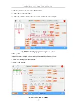
3. Manual Setting
When the user knows the accurate relative pose of the coordinate system relative to the
Base coordinate system, the operation coordinate system can be set manually. After
selecting this feature, enter the name and pose of the newly created coordinate system,
and click the “Add Coordinate System” button to send the information of the newly
created coordinate system to the robot controller and display it in the coordinate system
table. After the calibration, the robot works in the Base coordinate system.
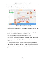
8.4.2.3 Setting Initial Pose
The initial pose of the robot can be set to facilitate the user to control the robot to reach
the position and pose quickly. As shown in the figure below, region 1 shows joint angles
of the initial pose established by the current robot. Region 2 is manually input by the
user. After setting the angles of the seven joints, click the “Set” button to send the set