


RealMan (Beijing) Intelligent Technology Co., Ltd.
25
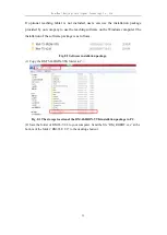
Fig. 5-6 Pin definition of aerial plug on tool end.
Pin #
Wire Color
Functionality
1
black
power GND
2
blue white
digital output 2 (DO2)
3
blue
digital input 2 (DI2)
4
green white
analog output channel (AO)/digital output 1(DO1)
5
green
analog input channel (AI)/digital input 1(DI1)
6
orange white
RS485_B
7
brown
RS485_A
8
brown white
digital GND
9
orange
power output: 5V/12V/24V; switch on and off is
controllable
Note that multiplexing function in the above table can be selected by the dialing switch
on the interface board circuit board. When switching the function, the interface board
needs to be taken out from the end of the robot arm, and the corresponding switch can
be dialed according to the dial switch identification on the interface board circuit board.
When leaving the factory, the default pin 4 is the analog output channel (AO), the pin
5 is the analog input channel (AI), and the power output of the pin 9 is 0V (can be set
by the program).
5.3.1 Digital I/O Input