


RealMan (Beijing) Intelligent Technology Co., Ltd.
69
3. Manual Setting of the Tool End Coordinate System
When the user knows the accurate relative pose of the tool with respect to the center of
the flange at the end of the robot, the tool coordinate system can be set directly by
manually entering the information. After selecting this feature, enter the name and pose
of the new tool, and click the “Add Tool” button to send the new tool information to
the robot controller and display it in the tool table. After the calibration is successful,
the robot operates in the tool coordinate system of the center of the end flange.
4. Payload at the End
After the tool calibration, we need to enter the weight and center of gravity position of
the end tool to make the tool parameters at the end of the robot arm more durable.
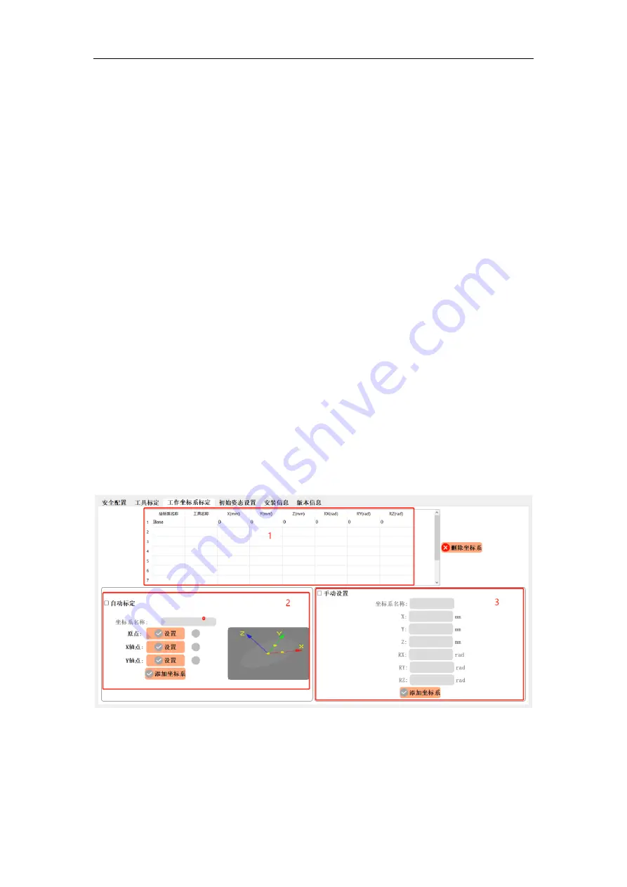
8.4.2.3 Calibration of the Operation Coordinate System
The calibration of the operation coordinate system is shown in the figure below. Region
1 displays the names of all the current operation coordinate system and Its positions
and poses relative to the Base coordinate system. Region 2 automatically calibrates the
current operation coordinate system. Region 3 manually sets the information of the
operation coordinate system.
Fig. 8-56 The calibration of the operation coordinate system.
1. Operation Coordinate System Display
The names and pose parameters of all the operation coordinate systems established by
the current robot are shown in the table. If you want to delete a coordinate system, select


