background image

RealMan (Beijing) Intelligent Technology Co., Ltd.


23 


Analog input 

Min 

Typical 

Max 

Unit 

input voltage 

-0.5 

12.5 

detection range 


10 

resolution 

12 

Bit 

5.2.4 Analog Output 

The controller has 4 analog output channels or ports. Its voltage range is 0~10V. Its 

electrical characteristics are shown in the table below. 

Analog output 

Min 

Typical 

Max 

Unit 

output voltage 

10 

port output current 


ma 

resolution 

12 

Bit 

5.3 The Tool End Interface Board 

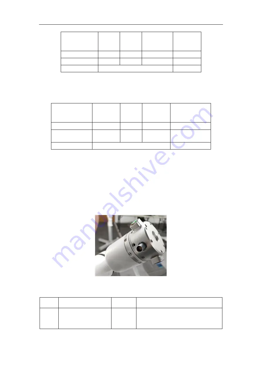
To facilitate the users to add tools to the end of the robot arm, i.e., wrist 3 (joint 6), a 9-

pin connector beside the tool flange at the tool end of the cooperative robot arm can 

provide power and control signals for the different grippers and sensors connected to 

the robot. Besides, there are two buttons on the flange shell to control the robot arm for 

teaching by dragging and trajectory reproduction, respectively. 


Fig. 5-5 The arm-end tool interface. 

The description of the interface board is shown as follows. 

Interface Type 

Quantity 

Functionality 

power output 

configurable from 5V/12V/24V; switch on 

and off is controllable 

Содержание RM65-B

Страница 1: ...RealMan Beijing Intelligent Technology Co Ltd 1 RealMan RM65 B Robot Manual V1 8 RealMan Beijing Intelligent Technology Co Ltd...

Страница 2: ...2 2020 06 15 Add intro of graphic online coding V1 3 2020 07 21 Add intro of bottom electrical board V1 4 2020 08 20 Revise intro of aviation plug order on the electrical board of the robot arm end V1...

Страница 3: ...19 5 2 Controller I O 20 5 2 1 Digital Input 22 5 2 2 Digital Output 22 5 2 3 Analog Input 22 5 2 4 Analog Output 23 5 3 The Tool End Interface Board 23 5 3 1 Digital I O Input 25 5 3 2 Digital I O O...

Страница 4: ...oject Load 45 8 3 3 Project Creation 46 8 3 4 Project Save 46 8 3 5 Project Content Display 47 8 3 6 Automatic Setting of a Programmable Point 47 8 3 7 Manual Setting of a Programmable Point 48 8 3 8...

Страница 5: ...RealMan Beijing Intelligent Technology Co Ltd 5...

Страница 6: ...rs can build their own robot control system by accessing the APIs of our collaborative RM65 B Besides this product also provides programmable operating software through which users can monitor the rea...

Страница 7: ...provide for your safety It is crucial and the instructions shall be followed Table 2 Warning Signs and Instructions Sign Instruction An impending hazardous electrical condition that if not avoided can...

Страница 8: ...mation is introduced in other sections of the manual However it is impossible to cover everything In practical applications specific issues need to be analyzed accordingly Table 3 Safety Precautions 1...

Страница 9: ...ting safety related hyperparameters After the safety related factors are modified the related safety features need to be double checked 8 In case of an accident or abnormal operation of the robot the...

Страница 10: ...t used during the installation 10 Do not modify the robot Non authorized changes to the robot can create dangers that the integrator cannot predict The authorized change of robot shall be in accordanc...

Страница 11: ...aws regulations and safety codes and standards of the host country or region Risk assessment is one of the most important tasks that must be performed by an integrator An integrator can perform the ri...

Страница 12: ...ted hazards pose an unacceptable risk including but not limited to The use of sharp actuator or tool connectors which may be dangerous Handling toxic or other hazardous substances The operator s finge...

Страница 13: ...the robot is hoisted proper measures and positioning should be taken for the moving parts so as not to cause accidental movement and damage during hoisting and transportation Before transportation th...

Страница 14: ...Technology Co Ltd in accordance with the regulations of the manual Assure the required safety level for maintenance and repair Comply with national or regional safety regulations Test whether all saf...

Страница 15: ...ntenance is accomplished 3 Keep maintenance records in the technical documents related to the whole robot system 4 The controller has no parts that users can repair by themselves Please contact your s...

Страница 16: ...erves the right to charge the customer for the replacement or repair Outside the warranty period we as RealMan Beijing Intelligent Technology Co Ltd shall not be liable for any damage or loss such as...

Страница 17: ...y Co Ltd 13 Use the product in radioactive equipment biological test equipment or in the use that we as RealMan Beijing Intelligent Technology Co Ltd judge to be dangerous 14 Failures other than the m...

Страница 18: ...that has six rotating joints each representing one degree of freedom DoF As shown in Figure 5 2 the robot joints include shoulder joint 1 shoulder joint 2 elbow joint 3 wrist 1 joint 4 wrist 2 joint 5...

Страница 19: ...2 core power cable the brown core is the positive power supply and the blue core is the negative power supply The robot arm also integrates a variety of communication interfaces for data transmission...

Страница 20: ...upgrade software import and export files 6 USB port 2 control the robot arm 7 Ethernet 1 connect to ethernet devices 8 Ethernet 2 connect to teaching devices and remote access 5 2 Controller I O There...

Страница 21: ...g output channels 0 10 volts 12 green white AOUT2 13 red white AOUT3 14 purple white AOUT4 15 yellow AIN1 Analog input channel 0 10 volts 16 brown AGND Analog ground 17 gray DIN1 Digital output channe...

Страница 22: ...l power to provide the power reference for the digital input Electrical characteristics are shown in the table below Digital input Min Typical Max Unit input power Vin 0 5 24 Volt or V input voltage 0...

Страница 23: ...ace Board To facilitate the users to add tools to the end of the robot arm i e wrist 3 joint 6 a 9 pin connector beside the tool flange at the tool end of the cooperative robot arm can provide power a...

Страница 24: ...press then the robot arm begins the teaching by dragging mode 8 trajectory repetition button in blue 1 short term press then the robot arm repeats the trajectory recorded by dragging The tool end inte...

Страница 25: ...When leaving the factory the default pin 4 is the analog output channel AO the pin 5 is the analog input channel AI and the power output of the pin 9 is 0V can be set by the program 5 3 1 Digital I O...

Страница 26: ...voltage 0 10 V output current 0 1 mA resolution 12 Bit 5 3 5 Power Output The tool end of the robot arm can output 5V or 12V or 24V power supply When the output voltage is 24V the actual output volta...

Страница 27: ...emperature is 0 C 45 C Required operating humidity is 25 85 no condensation Regarding floor load carrying capacity please mount the robot on a solid surface that is strong enough to withstand at least...

Страница 28: ...ce above and below the robot and avoid moving the tools into the cylinder space as much as possible Moreover the rotational range of each joint in practical applications is listed as follows i e rotat...

Страница 29: ...very low 2 It is recommended that the user use base surface with large heat dissipation such as all aluminum material When the operating environment exceeds 35 C it is strongly recommended that the u...

Страница 30: ...Before Power On Unpack and install the RM65 B robot to the base Please refer to Chapter 6 Robot Installation for the detailed installation instructions 1 Ensure that the robot arm and cable do not co...

Страница 31: ...is not connected Ensure that the robot does not bump into nearby people or equipment Make sure the power cable is connected to a 24V DC power supply Press the power button The power indicate light tur...

Страница 32: ...er of Windows operation system to install the teaching software Through this human computer interaction interface you can operate the robot body and controller execute and create robot programs and re...

Страница 33: ...ig 8 3 The storage location of the RM 65 IRON VTK installation package in PC 2 Save the folder of RM 65 V2 8 to your computer Send the file RM_ROBOT exe at the bottom of the folder RM 65 V2 8 to the d...

Страница 34: ...teaching panel is used for robot teaching operation Users can move the robot joints by clicking on the icon on the panel This panel also demonstrates the information about the robot s movements to th...

Страница 35: ...described as follows in the order shown in Table 5 8 2 1 Full screen Button This button is used to control the teaching software into and out of full screen Fig 8 7 The full screen button 8 2 2 Power...

Страница 36: ...5 Position Control The position of the robot arm end can be controlled based on the Base coordinate system the tool coordinate system Arm_Tip and the customized coordinate system The user can teach t...

Страница 37: ...remains unchanged while the pose changes around the specified coordinate axis denotes rotating to negative x axis direction denotes rotating to positive x axis direction Fig 8 12 The pose control pan...

Страница 38: ...on Its parameters and the moving status image of the robot arm will be displayed on the interface When the simulation mode is selected the robot does not move but its 3D simulation To finalize a robot...

Страница 39: ...l take the coordinate system as shown in Fig 8 15 as the Base coordinate system Users can also create their own operation coordinate system as the reference direction of the robot movement to meet act...

Страница 40: ...wn menu and select the coordinate system of the flange center by default see Fig 8 17 Users can also set customized tool coordinate systems Assuming that tool1 is the tool coordinate system set by the...

Страница 41: ...or touching the tablet interface according to the needs Fig 8 19 The 3D simulation model 8 2 12 Step Mode Setting To increase the teaching accuracy step control model is used which can make the contr...

Страница 42: ...trol is only effective for robot end and joint control Fig 8 20 Step mode demo 8 2 13 Robot Position and Pose Parameter Display The position X Y Z denotes the center of tool flange the selected tool c...

Страница 43: ...lso freely set the initial position and pose of the robot according to the descriptions in the section of the initial pose calibration Section 8 4 2 4 through the teaching software Release the button...

Страница 44: ...o realize the complex robot movement Fig 8 24 The online programming panel Table 6 Online programming panel Name 1 project file path selection button 2 import project button 3 new project button 4 sav...

Страница 45: ...blocks keys are described as follows in the order shown in Table 6 8 3 1 Project Selection For the created project click the Select Project button then select the project path and click Open and the f...

Страница 46: ...the gray box 3 Click Load button and the project will appear in the project content display area Fig 8 26 The project load panel 8 3 3 Project Creation After clicking button the project content displa...

Страница 47: ...ine MOVEL linear motion command Move the robot TCP to a given target point along a straight line It is suitable for the occasions where the high precision of the path is required such as cutting gluin...

Страница 48: ...int angles of the target pose When MOVEL or MOVEC is selected it moves in Cartesian space The text box below it displays the position and pose data of the target When you select Wait it waits a certai...

Страница 49: ...a programmable point 8 3 8 Insert Points Before the Current After recording the programmable points manually or automatically clicking the button will insert the newly created points before the curren...

Страница 50: ...the project content display column and add it after the line of program 8 3 10 Copy Click the button to copy the instruction and location information of the selected line 8 3 11 Paste Click the butto...

Страница 51: ...int Check Automatic edit and click the button the panel will automatically jump to the robot teaching interface Fig 8 32 Automatic editing a programmable point You can re teach the points After the te...

Страница 52: ...point Click the button to record the position of the re taught point and complete the point editing Fig 8 34 Updating a programmable point With the final point parameters known you can check Manual E...

Страница 53: ...e deleted in the display area on the left and then click button Fig 8 36 Deleting a programmable point 8 3 14 Move the Joint to the Current First click the target point at the left programmable point...

Страница 54: ...ps and then enter the number of loops on the right side 8 3 17 Start the Trajectory Tracking When online programming project is completed click the trajectory start point on the left side display area...

Страница 55: ...t of the trajectory at the left status area and the background color turns to green Then the user clicks the button and the button changes to a button with the pause function to complete the trajector...

Страница 56: ...rajectory tracking in order to avoid accidents caused by mishandling all the function of the interface are locked and cannot be used After pressing keys at the interface can be used properly 8 3 21 Te...

Страница 57: ...the track Teaching by dragging has four modes current loop position only pose only and pose position combination of four ways the latter three modes need six axis force sensor Fig 8 39 Teaching by dr...

Страница 58: ...ernal communication The network name is the WIFI name of the controller and the network password is the password of the controller s WIFI After clicking the Set button the controller will conduct netw...

Страница 59: ...e When the teaching software and the controller need to be connected directly through the Ethernet port the controller will communicate through the Ethernet port 2 IP address 192 168 1 18 port number...

Страница 60: ...ction between the computer and the controller the local network IP needs to be configured in the same network segment The configuration is shown below 1 Open Open Network and Sharing Center at the low...

Страница 61: ...Fig 8 43 Local connection 3 Click the Properties button in the dialog box that pops up Fig 8 44 Select the Properties button of local connection 4 In the pop up dialog box select Internet Protocol Ver...

Страница 62: ...g to the following figure Click OK button to complete the local network setting after the configuration Fig 8 46 The Internet IP address 6 Click the Configuration System Configuration Connect Robot Ar...

Страница 63: ...s of the robot arm end as shown in the figure below Fig 8 48 The safety configuration 1 Joint Configuration Select joints 1 6 in the left drop down box corresponding to the six joints from bottom to t...

Страница 64: ...ikewise 1 Select joint 1 from the leftmost option 2 Click the Enable button on the right Fig 8 50 Enable a joint Set the origin when the joint is in the disenabled status click the button and set the...

Страница 65: ...must be reset Example of setting origin Set the origin of joint 1 and the origins of other joints can be set likewise 1 Select joint 1 from the leftmost option 2 Click the Disenable button on the righ...

Страница 66: ...ot arm After the network connection between the teaching software and the robot controller is established this feature will automatically update the TCP parameters of the current robot and the user ca...

Страница 67: ...s of the robot must be recalibrated otherwise the situation of false collision will also occur 4 Installation Method There are three ways to install the robot arm i e lifting mounting and side mountin...

Страница 68: ...matically calculate the current tool information according to the 6 points After the calculation is completed it will be sent back to the teaching software and displayed in the tool list In addition d...

Страница 69: ...libration we need to enter the weight and center of gravity position of the end tool to make the tool parameters at the end of the robot arm more durable 8 4 2 3 Calibration of the Operation Coordinat...

Страница 70: ...are and displayed in the coordinate system table In addition due to the memory limitation of the robot controller only 10 operation coordinate systems can be saved So please make sure that the number...

Страница 71: ...mation System information includes controller status and joint status as well as system logs System information including controller input voltage output current temperature pose and error code Robot...

Страница 72: ...n the IO interface of the teaching software as shown in the figure below Fig 8 59 The I O configuration interface Digital Input This section displays the status of digital IO inputs with gray circles...

Страница 73: ...O Configuration In the IO interface of the tool panel of the teaching software the IO status and configuration of the tool can be displayed The output voltage of the tool end can be switched And simpl...

Страница 74: ...from the robot arm end interface board which can be configured with 0V 5V 12V and 24V External equipment by default gripper and dexterous hand can be added at the tool end and other devices can be add...

Страница 75: ...le point i e point1 5 Go to Teaching the Robot panel and move the robot to the first target programmable point of point1 Fig 9 2 Teaching the robot to point1 through the teaching panel 6 Back to Onlin...

Страница 76: ...8 Insert the second programmable point with a control method of e g MOVEL 9 Name it as point2 Fig 9 3 Automatic setting a programmable point i e point2 10 Go to Teaching the Robot panel and move the...

Страница 77: ...point3 14 Go to Teaching the Robot panel and move the robot to the third programmable point i e point3 15 Back to Online Programming interface and click Record the Current Point button 16 Click the Ad...

Страница 78: ...method is MOVEJ the Angle Setting will appear below 3 Input the name of point5 4 Set the joint angles to the desired joint angles Note the joint angles filled in shall not exceed the joint limit value...

Страница 79: ...it as the control method 8 Give a name i e w 9 Set the time to 3 seconds 10 Click Record Point button 11 Click the Add to After button to add the point to the list on the left Fig 9 8 Manual setting t...

Страница 80: ...Point button 16 Click the Add to After button to add the point to the list on the left Fig 9 9 Manual setting a programmable point i e point6 Edit the point Suppose to make changes to an existed progr...

Страница 81: ...if you want automatically editing the point and click the Select Point button Fig 9 11 Automatic editing an existed point 6 Enter the next interface move the joint to the target position and click OK...

Страница 82: ...will be paused in the trajectory After the pause press the Continue button to continue the movement 3 Press the Single Step button to perform single step movement 4 Press the Stop button to stop the...

Страница 83: ...ough the USB flash drive The specific operation steps are as follows 1 Turn off the power supply of the robot arm 2 Copy the bin upgrade file provided by the manufacturer to the bin directory of the U...

Страница 84: ...in 70s so please be patient Please do not power off during the update 11 Technical Specifications Robot RM65 B DoF 6 Payload 5kg 11lbs Weight 7 2kg 15 9lbs Repeat Ability 0 05mm 0 002in Reach 610mm 24...

Отзывы: