-12-
Manual Burner
CAUTION Isolate the power and gas supplies before commencing work on the fire!
•
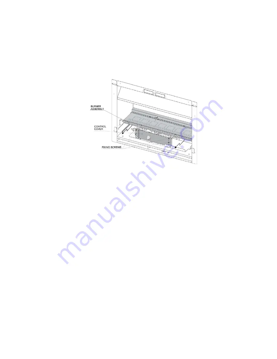
Remove the burner assembly by removing the two fixing screws in front of the burner and pull the tray
forward and then upwards to remove from the gas control.
•
There may be aeration sleeves attached to the venturi tubes on the back of the burner, take care not to
loose these, there is a chart on page 13 that shows which aeration sleeve should be used depending on
the gas and burner media being used.
•
Remove two fixing screws and remove the Gas Control Cover.
•
It may be necessary to remove the gas control assembly in order to make bending and flaring the gas
supply pipe easier. To do this remove the fixing screws on the bottom of the assembly and carefully lift
the assembly out.
•
After bending and flaring the gas supply pipe, purge the gas pipe and fix the gas control assembly back
in place and connect the gas.
•
Reconnect the gas.
•
Replace and fix the burner assembly in place
•
Connect a manometer to the inlet test point (refer page 13)
•
Rotate the Control Knob on the Gas Control to the pilot position push in to make the spark ignitor
operate, gas will begin to flow to the pilot.
•
The pilot should ignite within a few seconds. Note:
If the pilot fails to ignite, return the Knob to its original
position and try again. It may take some time to purge all the gas in a new pipeline.
•
Once the pilot is alight, hold the knob in for 5~10 seconds before releasing. The pilot should remain
alight.
If the pilot goes out again, repeat the ignition sequence again. If the pilot fails to stay alight after
15 seconds then proceed to the Trouble Shooting section (page 22)
•
Rotate the knob counter-clockwise until it stops at its maximum position, gas will begin to flow to the
main burner.
•
Once the burner has fully lit, check the Inlet pressure
o
1.0 kPa for Natural Gas
o
2.5 kPa for LPG
Adjustment can be made on the inlet pressure regulator
•
Turn the burner off and move the manometer to the Burner Pressure Test Point. Relight the burner and
check the maximum burner pressure against the data plate. Adjustment is made using the Burner High
Pressure Set screw on the side of the gas control.


