background image


EPSILON ES2,ES4 


21

!


WARNING! 

Calibration of the tank must be made using the same type of fuel, 

with which the sensor will be operating (for example, you can not use petrol 
for calibration, if you intend to operate with diesel fuel).  


To achieve the most accurate operating features of the sensor it is desirable to make “training”. 
It is sufficient to perform the calibration procedure not immediately after installation of a sensor, 
but after some time of car’s usage, when 50 – 70% of tank’s fuel capacity is used. During this 
time, mechanical clearances will normalize, guaranteed by the rubber gasket flange and a 
polymer sealant, and on the entire surface of the probe a stable dielectric fuel film is formed. 

If the "training" of the sensor can not be performed, before the calibration of the tank by filling it 
with use of a new sensor (probe), the probe must be immersed into the fuel than removed and 
you should allow the fuel to drain for 20-30 minutes. If the calibration is performed by the 
method of draining, this procedure is not performed. 

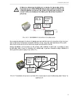
At the time of calibration you must disconnect the sensor from the on-board controller and 
connect it to the port of used PC (requirement to PC and port converter are shown in Table 5). 
At the end of calibration a connection to the on-board controller should be restored. 

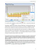
The result of calibration in the form of tank calibration table and user’s data about work 
executed is storing on the PC in a format which guarantees the data exchange into Dispatch 
Software. Detailed procedure of calibration using software application eS Install is described in 
Appendix 1. 
 

   10.  Maintenance  

 
The sensor is unattended product, but if the rules of vehicle maintenance provide the procedure 
of fuel tank prevention; it is advisable to execute simultaneously preventive service of the 
sensor. 

For sensor’s preventive service you have to: 

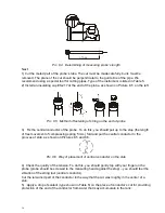
  Perform a complete removal of the sensor (see Pic.10.2); 

  Wash the probe from inside by the fuel (in which sensor is operating) and blow with 

compressed air. 

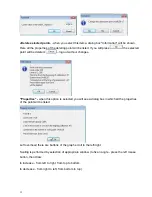
  Check own parameters of the measuring head (by using "eS Install"). 

  Perform installation and sealing of the sensor according to the requirements of section 8. 

Measuring head of the sensor is not repairable product and during the warranty period 
preserves the stability of its metrological parameters. 
 
In the case of failure of the measuring head you must perform the following: 

  If you want to use vehicle before a new measuring head is installed, it is necessary to make 

a partial removal of the sensor (see Pic. 10.1). 


Содержание EPSILON ES2

Страница 1: ...Fuel Level Sensor EPSILON Models ES2 and ES4 Service manual...

Страница 2: ...OR SENSOR S INSTALLATION AND CALIBRATION 9 6 1 Instrumentation 9 6 2 Equipment tools and consumables 9 7 STRUCTURE AND WORK OF SENSOR 10 7 1 Structure of FLS 10 7 2 Work of FLS 11 8 INSTALLATION 13 8...

Страница 3: ...F SENSORS ES4 TO ONBOARD MONITORING CONTROLLERS OF TRANSPORT SERIES GSM 48 6 CONNECTION OF SENSORS ES4 TO CONTROL UNIT OF MANAGEMENT SYSTEM OF TRANSPORT NAVIGATION TELETRACK 50 7 CONNECTION OF SENSORS...

Страница 4: ...or and to the staff that is responsible for the equipment of place where the work will be performed At the place of work fire safety rules should be kept in accordance with GOST Ukrainian 12 1 004 Fir...

Страница 5: ...exchange on the interface RS 485 2 Explosion Protection The sensor is explosion protected and it has such explosion protection marking 1Exm ia IICT6 for use in Russian Federation 1ExsiaIICT6 X for us...

Страница 6: ...level in static mode not worse mm 0 05 5 Basic permissible error in level measuring in static mode no more mm 0 5 6 The period of measurement results averaging in a dynamic mode s 8 Bit code represen...

Страница 7: ...f the calibration table should be applying according to the temperature dependence of the dielectric permeability of fuel It is also possible to adjust the calibration table with use of fuel with a di...

Страница 8: ...crew 9 64219 2 4 8 Gasket 5320 382713 1 9 Passport ES 402 1 10 Indicator s seal SILTECH 2 With wire for sealing 11 ZIP String 1 4 2 Extra Accessories Table 3 Name Decimal number Notes 1 Service manual...

Страница 9: ...6 1 Instrumentation Table 4 Name Quantity 1 Multimeter M890G 1 2 Tape measure 3 m 1 3 Measuring cup or flow meter providing measuring errors of fuel volume not worse than 0 1 1 6 2 Equipment tools and...

Страница 10: ...of free hard disk space the manipulator mouse a free USB port 1 10 Adapter for connecting of the sensor eS2 to the PC 1 11 The converter USB RS 485 model MOXA UPort 1130 for calibration of the tank w...

Страница 11: ...s provided by such facilities fuse for protection against overloads and short circuits intrinsically safe measuring circuit with normalized values of voltage inductance capacitance and resistance mult...

Страница 12: ...ation of the amount of controlled fuel the procedure of calibration of fuel tank should be carried out During this procedure the dependence between the amount of fuel and its level measured by sensor...

Страница 13: ...of the sensor Pic 8 1 Proper position of sensor on fuel tank It is necessary to clean the fuel tank in the place of sensor s installation WARNING Before sensor s installation on the tank firstly you...

Страница 14: ...ange WARNING You must remove the chip from drilling of the holes and also make sure that there are no foreign objects and trash on the tank bottom Lubricate both sides of the gasket 5320 382713 and se...

Страница 15: ...Light trucks and vans corresponds to outer height of tank mm in place of sensor s installation Type of the probe is indicated in the description of the sensor at the time of ordering In case of absenc...

Страница 16: ...ould pull up to the stop the length of free movement of compressing spring 5 mm fold and put the central conductor to the grooves of stub as shown on Pictures 8 5 and 8 6 Pic 8 6 Way of placement of c...

Страница 17: ...mended to use the original sensor s cable system which consists of an interface cable ES 120 0 45 m and a connecting cable ES 300 7 5 m The interface cable is connected to the measuring head of the se...

Страница 18: ...n earth conductors of the sensor black wire and of a control unit must be connected to a single point on the chassis of a vehicle to which mass or earth of the other electrical appliances of a vehicle...

Страница 19: ...mmon wire to the mass should not exceed 0 5 Ohms In any case the total resistance of the earth wires from the sensor to the control unit should not exceed 0 5 Ohms During installation of the sensor to...

Страница 20: ...the seal we recommend to drag it to hermetic output and press with a plastic electro technical clamp tie 9 Calibration To ensure the most accurate control of fuel level tank calibration is performed...

Страница 21: ...PC requirement to PC and port converter are shown in Table 5 At the end of calibration a connection to the on board controller should be restored The result of calibration in the form of tank calibrat...

Страница 22: ...the sensor sealing in accordance with the requirements of section 8 Partial removal of the sensor is made as follows Disconnect the interface and connecting cables Remove only the measuring head of t...

Страница 23: ...must be complied 12 Warranty Warranty period of operation of the sensor is 18 months from the date of entry into operation of the sensor but not more than 24 months from the date of production Date o...

Страница 24: ...Table 1 of section 3 of this manual After launch in the window eS Install you have to select the desired COM port and set the exchange speed By default the sensor with factory settings has the exchan...

Страница 25: ...data with the help of a button Load calibration data you can analyze the efficiency of the product in real terms If you download calibration data you will be able to estimate the fuel level not only...

Страница 26: ...riodic issuance of the data By default is not activated Repeat Interval defines the repeat interval during periodic issuance in seconds Turn on averaging activates averaging of the data Exchange speed...

Страница 27: ...on BACK Next to continue the work calibration you should choose the length of the probe after measuring the depth of the tank After that you need to screw the probe to the measuring head If the probe...

Страница 28: ...figures of percentage value Sensors of modifications ES2X ES2XL ES2XXL ES4X ES4XL ES4XXL are produced according to given ranges of probes length and do not need calibration The program automatically d...

Страница 29: ...g the protocol the tab Data Protocol will open Data made on this tab are complementary and they are used by technical support service They do not affect to the calibration but are saved in the cap of...

Страница 30: ...hod However if the vehicle was in operation and the fuel level is not the same as the last point of calibration you should add reduce fuel to the nearest calibration point guiding by code of level N I...

Страница 31: ...ses the maximum value for type 710 is N 4095 The information about each saved calibration point is displayed on the graph For taking extend information you have to click the left mouse button on the r...

Страница 32: ...hout changes Properties when this option is selected you will see a dialog box in which all the properties of the point will be listed Left overhead there are buttons of the graph scroll to the left r...

Страница 33: ...Auto save mode For saving the history and increasing the accuracy of the data processing it is recommended to allow auto save especially in the tanks of complex shape Changing of parameters of the pro...

Страница 34: ...5 ms Reaction time to reading command of supply voltage is approximately 250 ms The reaction time to the command of parameters saving is no more than 200 ms To avoid hanging during an unexpected seria...

Страница 35: ...on Note 27 from Dallas Multi byte command parameters are transferred in order from a junior byte to a senior one low endian A2 3 2 Description of computer code A2 3 2 1 Common commands for FLS of all...

Страница 36: ...fuel level 6 2 0000h FFFFh Technological value of fuel level 8 1 00h FFh CRC8 Turning on of the periodic data output is performing by command 55h In case of receiving of any valid command periodic da...

Страница 37: ...3Fh Rough calibration 12 1 00h Reserved 13 2 0000h FFFFh Exact calibration 15 1 F1h Reserved 16 1 00h Reserved 17 1 00h FFh Network address 18 1 00h FFh Period of data output 1 s 19 1 See table 4 2 D...

Страница 38: ...2 1 42h Command code 3 1 00h FFh CRC8 Answer format Drift byte Size of field byte Value Description 0 1 3Eh Prefix 1 1 00h FFh Network address of sender 2 1 42h Command code 3 1 00h FFh Year of produ...

Страница 39: ...ata output Command format Drift byte Size of field byte Value Description 0 1 31h Prefix 1 1 00h FFh Network address of acceptor 2 1 54h Command code 3 1 00h FFh Value of the period of data output 1 s...

Страница 40: ...mand code 3 1 00h or 01h Return code 00h command is complied successfully 01h Error 4 1 00h FFh CRC8 Data output mode decoding Bit s Use Description Value by default Notes 7 Output data capacity 0 10...

Страница 41: ...ded software versions 4 6 4 7 4 10 and higher For ES2 ES4 with software versions 1 3 1 4 bits 1 6 in the command parameter must be equal to 0 A2 3 2 1 8 Setting of network address command 56h Command...

Страница 42: ...00h or 01h Return code 00h command is complied successfully 01h Error 4 1 00h FFh CRC8 A2 3 2 2 2 Exact calibration command 49h Command is designed for exact calibration zero installation in the proc...

Страница 43: ...7h Parameter of probe s length 4 1 00h FFh CRC8 Probe s length parameter decoding Value of probe s length parameter Manufacturer s type mark Allowable length of probe mm Notes 0 User s L 0 260 Calibra...

Страница 44: ...00h 07h Parameter of probe s length look table 4 3 4 1 00h FFh CRC8 Answer format Drift byte Size of field byte Value Description 0 1 3Eh Prefix 1 1 00h FFh Network address of sender 2 1 4Eh Command...

Страница 45: ...me data output At the moment of receiving this command FLS shows data 1 time in the format described in P 5 1 DP switching on of periodic data output This command is sent only once after which FLS sho...

Страница 46: ...of model and interface Marking of measuring range Marking of maximum probe s length Coaxial ratio D d mm mm Probe s length mm maximum minimum ES2 ES4 0800 13 0 4 800 30 ES2 ES4 X 1208 13 0 4 1200 800...

Страница 47: ...displays needle indicator of fuel level and light indicator reserve A4 1 Connection For connection of sensors to the concentrator you need to use the Manual for installation of concentrator of fuel le...

Страница 48: ...Configuration of sensor Epsilon ES4 see pic A 4 3 pic A4 4 Data output capacity 10 bits Periodic data output is switched off Network address 1 for 1st sensor and 2 for 2nd sensor other values can be...

Страница 49: ...ith Appendix 1 A4 3 Configuration of concentrator DALCON see Pic A4 5 Pic A4 6 Periodic data output optionally Sensor 1 ask Sensor 2 ask You have to install network addresses of sensors in accordance...

Страница 50: ...4 4 Entry of calibration table see pic A4 7 pic A4 8 For empty tank 2 values of code are entered 0 automatic and the value got during the calibration for latter you have to establish the fuel volume o...

Страница 51: ...EPSILON ES2 ES4 51 Pic A4 8 Entry of calibration table for the 2nd sensor To use all the settings you need to switch off and restart DALCON...

Страница 52: ...ce parameters speed fuel level and condition of different vehicle sensors To connect to FLS RS485 port is used For connecting of 1 on more fuel level sensors to the range of devices A GSM you have to...

Страница 53: ...LS with onboard controller connector Teletrack on the connecting cable we set after installation a corresponding answer connector supplied with the control unit set Also you should use the manual of W...

Страница 54: ...liTrac A1 you have to use service manual IntelliTrac A1 series User Guide and following scheme ES2 RS232 3 2 4 2 3 4 5 8 9 6 10 2 3 4 5 8 6 According to manufacturer s manual for Intellitrack A1 for c...

Страница 55: ...bytes Asynchronous send Fuel data Using the IntelliTrac A1 with one FLS it is necessary during sensor s configuration to set the text format of the data Using the IntelliTrac A1 with the concentrators...

Страница 56: ...ransfer it to GSM networks To connect FLS use RS232 port Configuration of Teltonika FM4100 FM4200 and firmware To use FLS EPSILON you need special firmware and the configurator which can be supplied b...

Страница 57: ...S EPSILON calibration 1 Start the program eS Install see details in Appendix 1 2 On the tab Sensor s general options set following parameters of a measuring head Network address of device 1 Repeat int...

Страница 58: ...accordance with Appendix 1 Connection of the sensor to FM4100 4200 When configuration is complete the sensor can be connected to models Teltonika FM4100 or Teltonika FM4200 according to Pic A8 4 Pic...

Страница 59: ...sensor to the fuel M2M Cyber GLX should take leadership of the Terminal subscriber s GSM GLONASS GPS m2m cYBER glx Manual MDAV 464428 000 ER To connect the FLS port is RS485 or RS232 You can connect a...

Страница 60: ...RT PARITY Flow control no control Team UART FLOW 0 Test run UART FLOW Start and stop bytes does not matter After completing the configuration the user must enable the port to receive data from a comma...

Страница 61: ...after power up Termination of the waiting time of packets from the fuel gauge 30 seconds the default Team LLSFINISH DELAY 30 Test run LLSFINISH DELAY The calibration procedure FLS EPSILON 1 Run eS Ins...

Страница 62: ...2V ES4 RS485 5 9 4 8 2 6 3 1 10 12V Check can be done by monitoring the debug information output to the terminal program used to configure the device M2M Cyber GLX If the connection is properly config...

Страница 63: ...CARUS 702 702X and firmware To configure the program is used LOCARUS 702 702X U_Config Config900 from the device manufacturer To configure the device you must do the following Connect the equipment in...

Страница 64: ...guration to a file button The calibration procedure FLS EPSILON Run the program eS Install see details in Appendix 1 On the tab General Options sensor set the following parameters of the measuring hea...

Страница 65: ...2 702S according to the following figure 1 3 5 7 9 11 2 4 6 8 13 15 17 19 21 23 10 12 14 16 18 20 22 24 ES4 RS485 12V Functional test can be performed using the c U_InputTester InputTester900 supplied...

Страница 66: ...66 Turn on the unit Check the condition of parametric inputs assigned to the connected sensors...

Страница 67: ...BC817 R2 22 R1 10k TxD U ES 700 3 50 Diagram of the matching device to match the frequency output from the frequency of FLS and input device of vehicle monitoring output open collector the maximum lo...

Страница 68: ...traces of opening of head s body mechanical damage of the probe or the interface cable as well as traces of corrosive acids open flame high voltage lightning strikes or other natural factors Address o...

Отзывы: