


18
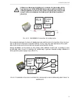
Pic. 8.8 Scheme of connection of interface and connecting cables
Additional instructions of connecting of the sensor to different control units, concentrators and
equipment of GPS - monitoring are in the appendixes of this Manual:
- for "
Dalcon"
concentrator – Appendix 4
- for
"АвтоГРАФ –GSM"
system – Appendix 5
- for
"Teletrack"
system – Appendix 6
- for
"IntelliTrac"
system
– Appendix 7
- for
"Teltonika"
system
– Appendix 8
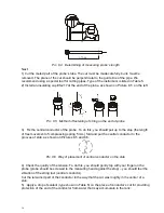
Common earth conductors of the sensor (black wire) and of a control unit must be connected to
a single point on the chassis of a vehicle, to which "mass" or "earth" of the other electrical
appliances of a vehicle are connected (Pic. 8.9).
ДУТ
БУ
-
Выключатель
массы
1
2
...
n
Э
л
е
кт
р
о
п
р
и
б
о
р
ы
Т
С
+
Pic. 8.9 CORRECT connection of common wire
Interface cable
Connecting cable
Yellow
Green
Red
Blac
k
embedded networ
k
general
ES4 ES2
Channel A (RS485) Rx(RS232 output 2 DB9)
Channel B (RS485) Tx(RS232 output 3 DB9)
ES4 ES2
Channel B (RS485) Tx(RS232 output 3 DB9)
Channel A (RS485) Rx(RS232 output 2 DB9)
FLS
Disconnect
Switcher
Electrical appliances of a vehicle
Control
block