


Series 1780 Dynamometer User Manual V1.1
Document ID: Q2D4F5
Publish date: 2020-03-06
●
12.70mm spacer - M4 x 20mm screw
●
22.23mm spacer - M4 x 30mm screw
●
33.34mm spacer - M4 x 40mm screw
●
38.10mm spacer - M4 x 50mm screw
Follow these instructions to install the optical probe onto the motor mount:
❏
Apply black electrical tape (prepared by you) to seal the logo on the rotor of the
motor to be tested.
❏
Apply the supplied reflective tape on any part of the rotor of your motor. The length
of the reflective tape should be longer than 10mm. For the motors that have larger
diameter, put a longer tape on the motor for measuring the RPM. Please note that if
you run out of the reflective tape provided by us, please use a white electrical tape as
an alternative.
❏
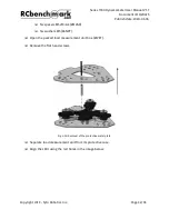
Select a pair of spacers and screws that correspond to the height from the motor
mount to the reflective tape.
❏
Place the M4 screw, the M4 black plastic washer through the slots on the optical RPM
probe. Then put the aluminum spacers on the other side of the circuit. Slightly fasten
the screws into the tapped holes on the motor mount.
Fig. 4.26: Connection of the screw, washer, spacers and the optical probe to the motor mount
Copyright 2019 - Tyto Robotics Inc.
Page 40/65


