

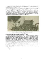


element, incased in its insulating material, may be noticed. This condition in no way affects the normal
operation of the Radiotron. The lag in the transference of heat from the heater element to the cathode, as
evidenced when starting and stopping the operation of the tube, takes care of any variations indicated by
this flicker, which supposedly might affect the normal operation of Radiotron UY-227. In Radiola 17
there is a positive potential of 9 volts applied to the cathode of Radiotron "UY-227 with the negative side
of this potential connected to the center connection of the potentiometer across the heater winding for this
Radiotron. This prevents a possibility of the cathode emitting any electrons back to the heater instead of
to the plate.
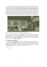
The power-amplifier Radiotron UX-171 in the last audio stage is interchangeable with the new
EGA Radiotron UX-171A. An output transformer protects the loudspeaker windings from the high plate
voltage used with this Radiotron.
Radiotron UX-280 is a full wave rectifying Radiotron used to rectify the alternating current into
pulsating direct current, which is smoothed out by means of a filtering system, and used to provide all
plate and biasing voltages.
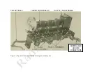
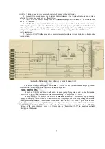
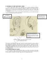
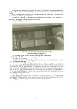
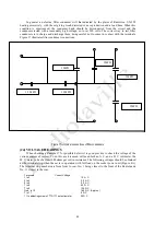
Figure
5—
Radiotron socket contacts
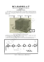
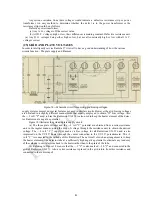
ANTENNA INSTALLATION (Outdoor Type)
Due to the high sensitivity of Radiola 17 the most efficient antenna system is one of
approximately 25 feet in length—depending upon local conditions—measured from the far end
of the antenna to the ground connection. It should be erected as high as can be conveniently arranged
and as far removed from all obstructions as possible. The lead-in should preferably be a continuation
of the antenna itself, thus avoiding all splices which introduce additional resistance to the antenna
system and which may in time corrode sufficiently to seriously affect reception. If, however, it is
absolutely necessary to splice the lead-in to the antenna, the joint must be carefully soldered to insure a
good electrical contact. Excess flux should be cleaned off and the connection carefully covered with
rubber tape to protect it from the oxidization effects of the atmosphere.
The antenna and lead-in should be supported by high grade glass or porcelain insulators. At no
point should the antenna or lead-in wire come in contact with any part of the building. The lead-in wire
should be brought through the wall or window frame and insulated therefrom by a porcelain tube. The
use of a flat "window-strip" type of lead-in is not recommended.
8
(4)