


CONTENTS
A Word or Two About Service ………
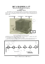
Introduction …………..........................
Service
Data
Chart................................
PART I—SERVICE DATA
PART II—MAKING REPLACEMENTS
ILLUSTRATIONS
Page
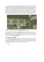
RCA Radiola 17 ...............„.............................:........ 1
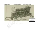
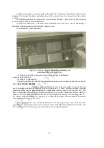
Top View of Chassis Assembly................................. 4
Socket Power Unit Showing Parts.................................. 5
Radiotron Sequence ................................................... 5
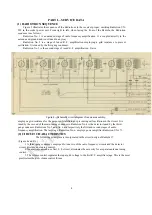
Schematic Circuit Diagram of Receiver………………. 6
Schematic Circuit Diagram of S.P.U.............................. 7
Radiotron Socket Contacts ........................................ 8
Method of Cleaning Radiotron Prongs.......................... 9
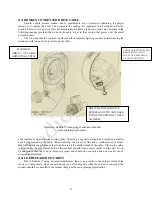
Releasing Volume Control ......................................... 10
Adjusting Contact Arm of Volume Control ................ 11
Turning Cable Adjusting Screw...... …………… .. 12
Condenser Cable and Drum Mechanism……………. 13
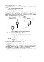
Schematic Circuit for Resistance Measurement.......... 14
Adjusting Potentiometer tor Minimum
Hum ............. 16
Page
View of Pilot Light Socket and Canopy.
…….….... 17
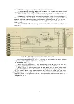
Wiring Diagram of Sub-Chassis Assembly
……....... 18
Continuity Wiring Diagram of S.P.U.......................... 19
Internal Connections of Filter Condensers ............... 20
Schematic Circuit
for
Securing
Grid
Voltages.......... 21
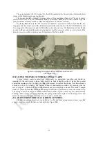
Removing Receiver Assembly fro
m Cabinet…… ….22
emoving Receiver Assembly from Cab-22
Page
2
5
32
Page
Radiotron Sequence .................................................... 6
Circuit Characteristics ................................................ 6
Radiotrons.....;.....................................................
7
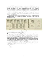
Antenna Installation (Outdoor)........................
8
Antenna Installation (Indoor)...........................
9
Ground ........................................;.............................. 9
Antenna System Failures .......................................
10
Radiotron Sockets...............:..............................
10
Radiotron Prongs........................................................ 10
Loose Volume Control Contact Arm..........
11
Adjustment for Slack Drum Control........
11
Mechanical Hum......................................................... 12
Broken Condenser Drive Cable........................
13
Loudspeaker Polarity .
Uncontrolled Oscillation
Distorted Reproduction
Audio Howl ......................
Acoustic Howl ........
Hum ............................
Line Control Switch ............
Wiring Cable .............................
Pilot Lamp and Canopy
Filter Condensers ..................
Voltage Readings ..................
Grid and Plate Voltages
Heating of Cabinet ...............
Continuity Tests .....................
Page
13
.
14
.... 15
..
I5
.... 16
... .16
......18
..... 19
..... 19
..... 20
..... 20
..... 21
..... 22
..... 23
Page
Replacing Volume Control ........................................... 24
Replacing Radio Frequency Coils................................... 25
Replacing Radiotron Gang Sockets................................. 26
Replacing Main Tuning Condensers and Drive …...... . 26
Replacing Large By-Pass Condensers............................. 27
Replacing Audio Transformers ....................................... 28
Replacing Output Transformer........................................ 28
Page
28
29
30
30
31
31
31
Replacing Condenser Drive Cable.........
Replacing Dial Scales............................................
Replacing Power Cable................................
Replacing Filter Condenser Assembly....
Replacing Either Power Transformer
or
Filter Reactor
Replacing Terminal Strip
Replacing Miscellaneous Parts in S.P.U....
R F. Transformer Connections...................................24
By-Pass Condenser Connections................................25
A. P. Transformer Connections..................................26
Output Transformer Connections...............................26
Replacing Dial Scales ...............................................27
Color Scheme of Power Cable Connections………. 29


