


(13) BROKEN CONDENSER DRIVE CABLE
Should a cable become broken, due to considerable use or excessive tightening, the proper
remedy is to replace the cable. The procedure for making this replacement is described in Part II,
Section 8. However if a new cable is not immediately available a temporary repair may be made in the
following manner provided the break in the cable is not in that section that passes over the small
grooved drums.
The two ends should be spliced together and then soldered. Splicing consists of interweaving the
strands as with rope and not just twisting the cable
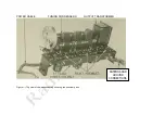
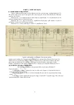
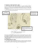
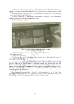
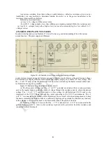
Figure
10
—
Radiola
17
three-gang condenser cable and
drum operating mechanism.
ends together as in an electrical wiring splice. Splicing gives greater strength and results in a smaller
body being formed on the cable. When soldering, use plenty of flux and a small amount of solder.
Heat sufficiently long for the solder to adhere to all the small strands of the cable.. Placing the splice
in an alcohol or bunsen flame affords sufficient heat and allows any excess solder to drip away. It is to
be understood that this is but a temporary repair and should be used only until a new cable can be
procured and installed.
(14) LOUDSPEAKER POLARITY
Due to Radiola 17 using an output transformer, there is no polarity to the output current of the
receiver. Consequently, when connecting any type of loudspeaker (either horn type or cone type) the
speaker should be connected in the manner that gives the most pleasing reproduction.
13
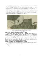
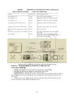
MAXIMUM
ADJUST OF CABLE
ADJUSTING SCREW
CABLE ADJUSTIJNG SCREQ
REMOVED TO ALLOW
HALF-TURN EXTENSION
OF CABLE ON DRUM
DOTTED LINES INDICATE
REFERSAL OF PIN AND HALF-
TURN EXTENSION OF CABLE
ON DRUM


