


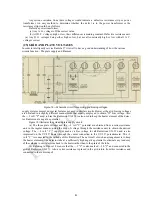


(15) UNCONTROLLED OSCILLATION
Should Radiola 17 oscillate or regenerate at any point in the tuning range the trouble is probably
caused by:
1. Defective grid resistor in second or third E. F. stages.
2. Excessive filament voltage.
3. Antenna lead too close to third E. F. transformer.
4. Detector tube howling.
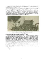
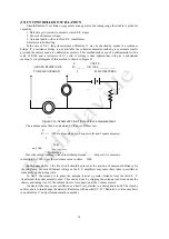
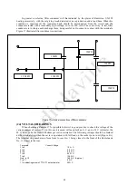
In the case of No. 1 the grid resistance of Radiola 17 may be checked by means of a resistance
bridge. If' a resistance bridge is not available the voltmeter-ammeter method gives accurate results
provided the meters used are calibrated accurately. This method makes use of a milliammeter with a
scale of 0-500 and a voltmeter of 0-7 volts. A voltage is then applied that will give a substantial
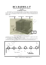
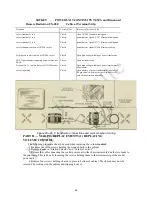
reading. A circuit diagram of this method is shown in Figure 12.
E VOLTS
ACROSS RESISTANCE
R= ______ OR 1000 ____________
TO BE MEAUSERED
I
MILLIAMPERES
V
0-7 6 VOLTS
0 - 500
Figure 12
—Schematic circuit for resistance measurement.
The resistance may then be calculated by the use of Ohms law.
E
R ==— (Where R equals ohms, E equals volts and I equals amperes)
I
Volts
or 1000 ___________
Milliamperes
1
Since the current reading is taken in milliamperes
(or
—— ampere) it is necessary
to multiply by 1000 to get the resistance value in ohms. 1000
In the case of
No. 2 the line switch should be placed at the position of minimum brilliancy for
the pilot lamp. Excessive filament voltage on the E. F. amplifiers may cause these tubes to oscillate at
some point on the tuning scale.
In No. 3 the remedy is to place the antenna lead at a greater distance from the third E. F.
transformer than that normally used. This can be done by slipping the antenna lead from under the
chassis and taking it out of the cabinet close to its connection at the volume control.
A detector tube may cause oscillation or a howl, very similar to a microphonic howl. The remedy
in this case is to interchange the detector Radiotron with another UY-227 Radiotron. A tube may howl
in one Radiola 17 and perform normally in another.
14
MA


