


6. Connect power cable to chassis assembly and give Radiola an operating test before returning to
the cabinet to determine that replacement has been properly made.
7. Return chassis assembly to cabinet and replace all screws and knobs.
(3) REPLACING RADIOTRON GANG SOCKETS
The Radiotron sockets of Radiola 17 are of the gang variety, using one detector socket, a two-gang
A.F. socket strip and one three-gang socket strip for the radio frequency amplifier tubes.
These sockets are riveted to the metal chassis.
To replace
them drill out the old rivets and use
screws, nuts and lock washers for securing the new sockets. A step by step procedure follows for making
a replacement:
1. Remove chassis assembly from cabinet as described in Part II, Section 1.
2. Remove and tag all leads to the terminals of the sockets.
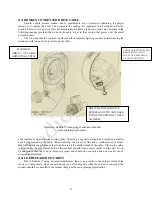
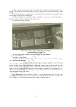
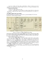
Figure
22
—
Detail
of A. F. transformer connections and
color
scheme of wiring.
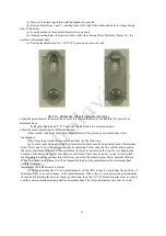
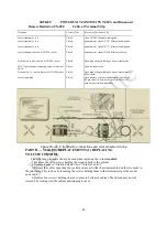
F
Figure
23
—
Output transformer
connections.
3.
Drill out rivets holding sockets to metal chassis frame.
4. The socket assembly may now be removed and the new one placed in the position occupied by the old one.
5. Fasten new socket in place by using small head machine screws, nuts and lock washers in place of the rivets
previously drilled out.
6. Replace connections as indicated on tags attached or refer to Figure 15 for the correct socket connections.
7. Connect cable and socket power unit and test Radiola.
8. Return chassis
to cabinet.
(4) REPLACING MAIN TUNING CONDENSERS AND DRIVE
The main tuning condensers and the driving mechanism is replaced as one complete unit. The step by
step procedure follows:
1. Remove chassis assembly from housing. See Part II, Section 1.
26
OUTPUT
TRANSFORMER
TERMINAL
STRIP


