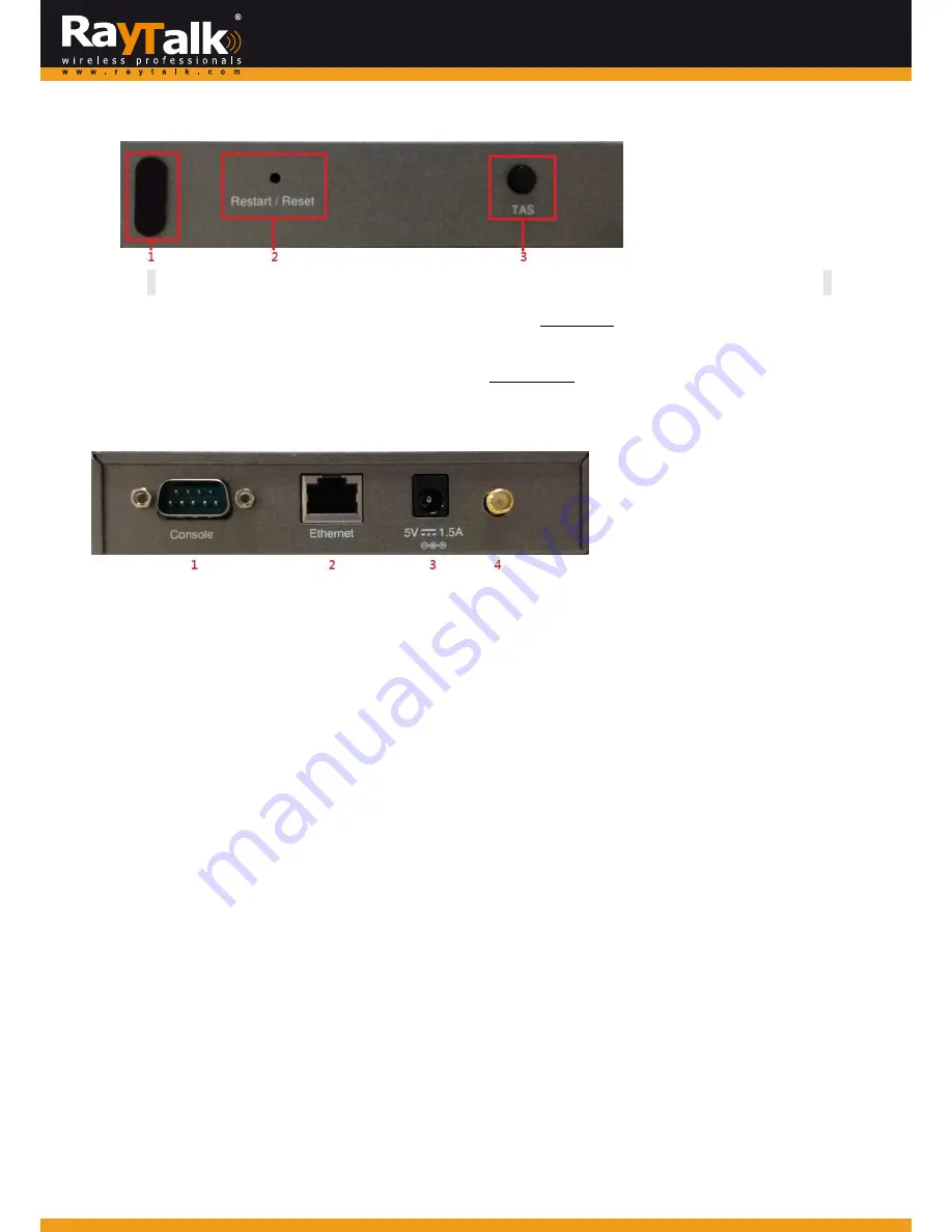
Right
Side
Panel
Overview
Right
Side
Panel
1.
Kensington
Lock
Be
used
to
lock
the
device
to
a
pole.
2.
Restart
/
Reset
Pole
once
to
reboot
the
system.
Poke
for
five
seconds
to
make
RT
‐
TO696RF
set
back
to
factory
default
settings.
3.
TAS
Terminal
Auto
Setup
(TAS).
Press
three
seconds
to
initiate
the
auto
uplink
connection
process.
This
will
be
introduced
later.
Left
Side
Panel
Overview
Left
Side
Panel
1.
Console
Serial
port
for
connecting
to
a
POS
printer.
2.
Ethernet
RJ
‐
45
Ethernet
port
Serial
port
for
connecting
to
the
uplink
gateway
via
wire.
3.
5V
/
1.5A
The
DC
power
socket
for
connecting
to
an
external
power
source
through
a
DC
power
supply.
4.
Antenna
connector
Assemble
the
dipole
antenna
within
the
package
here.
Including
RT
‐
TO696RF
into
Your
Network
1.
Put
relevant
devices
in
place.
2.
Attach
a
RT
‐
TO696RF
to
a
power
adaptor
provided
in
the
package.
3.
Attach
a
POS
printer
to
a
power
adaptor
provided
in
the
package
and
turn
on
the
power
switch
situated
on
the
left
side
of
the
device.
4.
Connect
a
POS
printer
to
the
Console
port
of
RT
‐
TO696RF
by
a
RS
‐
232
cable
provided
within
the
POS
printer
package.
5.
Connect
RT
‐
TO696RF
to
your
RayTalk
Internet
Subscriber
Gateways
via
Ethernet
port
or
wirelessly.
If
you
are
to
do
it
wirelessly,
conduct
a
site
survey
in
the
first
place.
The
wireless
coverage
is
subject
to
change.
6.
To
verify
if
the
deployment
works
fine.
Press
FUNC
+
‘1’
+
ENTER
to
see
if
RT
‐
TO696RF
is
attached
to
a
correct
gateway
and
get
an
IP
address
from
it.
Additionally,
press
‘Number’
+
ENTER
to
see
if
an
account
with
a
certain
billing
plan
can
be
printed
out.
If
it
is
not
working
properly,
go
to
Appendix
A
for
trouble
shooting.
145


