background image

 Installation

27

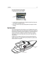
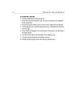
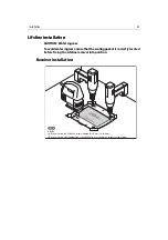
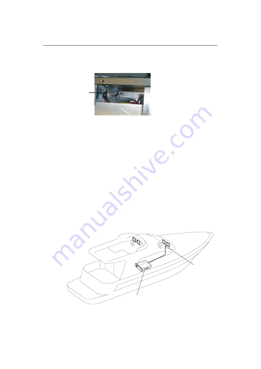
To remove thetransit securing clips:

1. Remove the top cover of the computer.


2. Locate the transit securing clip which is located to the right of the CD drive when 

the computer is viewed from the front.

3. Remove the transit securing clip by pulling it upwards and awayf rom the shock 

mounting.

System control

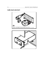
The normal operating sequence for H6 requires power to be applied to the system by 
pressing the on/off button on the front of the navigation computer. If the computer and 
interface units are installed some way from the helm (e.g. on another deck) this is not 
always easy or practical. Consideration should therefore be given to installing a 
remote power switch at the main helm which can be used as an alternative to the 
computer button.

Installation of this will require a cable to be run from the navigation interface unit - 
CON 29 and terminate in a suitable ON/OFF switch at the helm. This switch must be 
clearly annotated as to its purpose.


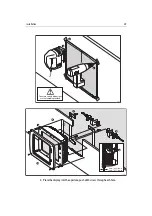
Transit 

securing clip

D7660_1

Remote ON/OFF

switch

Navigation computer

Main helm

D7597_1

Содержание H6

Страница 1: ...System Installation Manual Document number 87035_1 Date November 2004 D7579_1...

Страница 2: ...Autoseastate Autotrim Bidata Marine Intelligence Maxiview On Board Raychart Raynav Raypilot Raystar ST40 ST60 Seaclutter Smart Route Tridata and Waypoint Navigation are trademarks of Raymarine Limited...

Страница 3: ...System overview 7 Introduction 7 System overview 7 Planning the installation 13 Introduction 13 Installation sites 13 Safety of operation 14 Off vessel communications 14 Navtex 15 Television receptio...

Страница 4: ...n 33 Audio visual control unit 36 Power amplifier 38 Speaker units 39 System set up 43 Introduction 43 Initial system startup 43 Adjusting the display screen 44 H6 software setup 46 Online setup 47 Te...

Страница 5: ...pendix A ini file details 67 Installation checklist 91 Raymarine H6 World Wide Warranty 93 System component dimensions 99 Display unit connections 105 Inter unit connections 107 Installation templates...

Страница 6: ...4 Raymarine H6 System Istalation Manual...

Страница 7: ...carried out in accordance with the installation instructions contained in the relevant handbooks supplied with the equipment Installationofsystemoptionsandaccessoriesshouldbecarriedoutinaccordancewit...

Страница 8: ...on and entertainment computer main boards and lifeline transmitters have lithium batteries fitted Do not attempt to re charge these batteries Do not incinerate these batteries Check local regulations...

Страница 9: ...ical equipment For optimum EMC performance it is recommended that wherever possible Raymarine equipment and cables connected to it are At least 3 ft 1 m from any equipment transmitting or cables carry...

Страница 10: ...mentoftheinstallationtoensurethatthecorrectqualityofcableis used andthatmaximumlengthsasspecifiedinthishandbookarenotexceeded Valid proof of purchase of the correct cable type will be required for Ray...

Страница 11: ...rent data protocols SeaTalk and National Marine Electronics Association NMEA Data Interface Standard Data transfer fortheentertainment functions is achieved using compositevideo RGB RS232 and 5 1 Audi...

Страница 12: ...checking compatibility between items that the same sentence identifiers are used e g VTG carries Course and Speed Over Ground data GLL carries latitude and longitude DBT carries water depth and MWV ca...

Страница 13: ...to dedicated interface units which in turn pass it to the associated computer The computer processes the data which is then shown on the displays The user can set these displays to show information a...

Страница 14: ...A junction box Calibration instrument Entertainments core package The entertainments core package consists of the following components Entertainments computer Entertainments interface unit 12 channel...

Страница 15: ...6installationallof thecabintelevisionsandthesaloonentertainments screen will all show the same programme If the option of individual channels being availableinindividualcabinsisrequired itwillbenecess...

Страница 16: ...10 Raymarine H6 System Installation Manual...

Страница 17: ...11 This page should be replaced with the A3 sheet System Schematic...

Страница 18: ...12 Raymarine H6 Installation Manual...

Страница 19: ...that all of the different sections are available in the correct sequence at the right time Installation sites When planning installation sites for system components consider the following Ventilation...

Страница 20: ...nctions correctly Pathfinder radar unit The Pathfinder radar unit should be installed at the main helm adjacent to the H6 displays Alarms created in H6 can only be cancelled using the Pathfinder unit...

Страница 21: ...smissions worldwide Raymarine recommend the Marine Computing International 518 KHz antenna which is available from www marinecomputing com Television reception Consultation will be required with the c...

Страница 22: ...sed bulkhead or deckhead a watertight feed through should be used Secure cables in place using tie wraps or lacing twine Coil any extra cable and tie it out of the way Computer interface units and cor...

Страница 23: ...lt spray Ventilation To prevent any dimming of the displays by the in built active thermal management it will be necessary to provide adequate ventilation Wherever possible this should be ambient cabi...

Страница 24: ...ilation This airflow should be of a forced type if necessary Speaker units Position Thespeakerunitsshouldbeinstalledgivingconsiderationtotheeffects of surround sound in an enclosure packed with a suit...

Страница 25: ...talling the system cables You need to attach power cables and scanner cables Additional cables may be required for long cable runs All cables should be adequately secured protected from physical damag...

Страница 26: ...20 Raymarine H6 System Installation Manual...

Страница 27: ...21 This page should be replaced with the A3 sheets Cables...

Страница 28: ...22 Raymarine H6 Installation Manual...

Страница 29: ...Manufacturer s handbook accompanying the product Safety notices WARNING High Voltage This system contains high voltages Adjustments require specialized service procedures and tools only available to q...

Страница 30: ...d Do not attempt to re charge these batteries Do not incinerate these batteries Check local regulations when disposing of used batteries Ensure that they are replaced with a battery of the same type C...

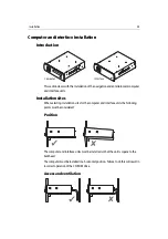
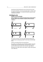
Страница 31: ...ting installation sites for the computer and interface units the following points must be considered Position The computer and interface units must be installed so that the unit is square to the bulkh...

Страница 32: ...ck mounts of both the avigation and Entertainments computers The computer and interface units must be supported behind the bulkhead when installed This can be achieved using suitable L section channel...

Страница 33: ...offbuttononthefrontofthenavigationcomputer Ifthecomputerand interface units are installed some way from the helm e g on another deck this is not always easy or practical Consideration should therefor...

Страница 34: ...onnected to the boat s ground or Floating with neither battery terminal connected to the boat s ground Grounding the displays It is important that an effective RF ground is connected to each display T...

Страница 35: ...unting hole 4 1 mm dia me ter 4 position s Remove shaded areas only 302 2 mm 11 9 in 391 6 mm 15 4 in center line Ins tru me nt edge Sun cover edge D7410_ 1 3 1 2 To ensure correct dimensions use the...

Страница 36: ...washer affix nuts and tighten 6 To each side of the display loosely attach in the following order i Metal washer ii Bracket iii Plastic washer iv Cam v Penny washer vi Spring washer vii M8 bolt 7 Oper...

Страница 37: ...a s o n l y H 6 T r a c k b a l l U n i t M o u n t i n g T e m p l a t e D r i l l h o l e 6 m m 1 4 i n d i a m e t e r i n 8 p o s i t i o n s F a s c i a e d g e C o v e r e d g e H o l e A H o l...

Страница 38: ...rill the eight 6 mm 1 4 in holes marked in the shaded area 4 Cut the aperture in the surface checking that there is nothing behind that the saw might damage 5 Ensurethatthesealinggasketiscorrectlyloca...

Страница 39: ...s c i a e d g e C o v e r e d g e H o l e A H o l e A H o l e A H o l e A D7323 1 R e m o v e m a t e r i a l f r o m s h a d e d a r e a s o n l y H 6 L i f e l i n e U n i t M o u n t i n g T e m p...

Страница 40: ...3 Using the template drill the eight 6 mm 1 4 in holes marked in the shaded area 4 Cut the aperture in the surface checking that there is nothing behind that the saw might damage 5 Ensurethatthesealin...

Страница 41: ...ositioninthe radar arch and one in a vertical position in either the engine room or a forward cabin On a sail boat one could be installed in the sail locker and one in the main accommodation To mount...

Страница 42: ...al from shaded areas only H6 AVC Unit Mounting Template Fascia edge Hole A Hole A Hole A Hole A 1 2 3 Hole A If you are using the Button Head screws supplied drill 6 mm 1 4 in holes If you are using S...

Страница 43: ...template drill a suitable size hole at each of the positions marked A for the securing screws 3 Using the template drill the eight 6 mm 1 4 in holes marked in the shaded area 4 Cut the aperture in the...

Страница 44: ...each of the positions marked A for the securing screws Fas cia edge D7319 1 UP Rem ove mat er ial from sh ad ed ar ea s only H6 Amplifier Unit Mounting Template Ho le A Ho le A Ho le A Ho le A 1 2 3...

Страница 45: ...und quality it is necessary to install the speakers in certain positions and ensure that they are acoustically insulated 5 1 surround sound Toenjoythefulleffectof5 1surroundsoundthespeakersshouldbeins...

Страница 46: ...97 58 mm 3 27 32 in 97 58 mm 327 32 in Cut hole 114 mm 41 2 in diameter Hole A Hole A Hole A Hole A PLEASE CHECK MEASUREMENTS ON TEMPLATE BEFORE USE D7324 1 D7421_1 Check Hole A If you are using the...

Страница 47: ...Sub woofer installation Drill hole 5 2 mm 7 32 in diam eter 4 positions Remove material from shaded areas only H6 Sub Woofer Unit Mounting Template Cut hole 189 mm 729 64 in diameter UP D73 25 1 D7423...

Страница 48: ...42 Raymarine H6 System Installation Manual...

Страница 49: ...instruments within the system are powered ON 2 Press the button on the front of the Navigation computer to start running H6 3 Press the power button on both displays to ON The H6 disclaimer is display...

Страница 50: ...Brightness volume and input source Note Raymarine H6 monitors do not have in built speakers monitor volume adjustment is partofthesoftwaresetup Thereforeadjustingthevolumeofthemonitorwillhavenoeffect...

Страница 51: ...tion They can be used for VGA inputs to adjust the horizontal and vertical position of the image on the screen Once commissioning is complete these controls do not normally need to be adjusted Vertica...

Страница 52: ...yed These files are found in the Setup directory and are named cam ini datasources ini setup ini It is strongly recommended that you make a copy of these files and place them in the Setupdirectory The...

Страница 53: ...rop down menu is displayed ii Select All Files All files in the directory are displayed 8 Double click cam ini The contents of the file open in Notepad 9 Modifythefilescriptasnecessary makingsurethati...

Страница 54: ...ou are asked to name the modem type in either GPRS or GSM The association is then made between the modem and the On line browser softkey 7 Complete installation as instructed by the wizard This proced...

Страница 55: ...ary to construct a short link with a jack plug at each end which is then installed between theAudio input and Line Out ports on the rear of the Entertainments computer as illustrated above Satellite t...

Страница 56: ...tered and available for use The registration screen will no longer appear at system power up If Navtex isnot required thesoftwaremustbedisabledby amendingthesetup ini file See ini file details on page...

Страница 57: ...ts appears 6 Select the area that you require charts for Placing the cursor over a chart number will causea pop up of thearea nameto appearandthearea will behighlighted on the main chart 7 Click the h...

Страница 58: ...want to purchase 12 Click Call Center in the toolbar at the top of the screen Contact details for C Map will be displayed 13 Contact C Map at the relevant center shown in the Call Center list and purc...

Страница 59: ...ter and will automatically be available through the C Map chart layer 18 Remove the CD ROM from the Navigation computer Maptech charts Installation of Maptech charts requires a keyboard they must ther...

Страница 60: ...cate Maptech charts that are installed on your system You then select which charts you require and install them using the chart manager To install charts using the chart manager With a chart window op...

Страница 61: ...on of each chart will be shown 6 The chart manager will update the chart list 7 Click OK The dialog box closes Instrument calibration CAUTION Chart and GPS datum The GPS must be set for WGS84 datum Ba...

Страница 62: ...56 Raymarine H6 System Installation Manual...

Страница 63: ...uipment Whenpoweredup allelectricalequipmentproduceselectromagneticfields These can cause adjacent pieces of electrical equipment to interact with one another with a consequent adverse effect on opera...

Страница 64: ...registered prior to use Check that the registration screen does not appear when H6 is started If it does you will need a license key to register the software On line does not work Youwillneedtohaveamo...

Страница 65: ...Check Radar transmit softkey is set to ON 2 Check that Pathfinder display has been powered ON Scanner not responding message Check that the cable connecting the scanner to the Pathfinder display is fi...

Страница 66: ...shut down Click Reset Lifeline Alarm will be cancelled and Lifeline system will reset Trackball Problem Possible solution Cursor stops following the trackball Move the trackball more slowly The curso...

Страница 67: ...een with a dry cloth this could scratch the screen coating Do not use acid ammonia based or abrasive products 1 Ensure the display is switched off 2 Wipe the display with a clean damp cloth 3 If neces...

Страница 68: ...snotrequireregularcleaning However if it is found to be necessary to clean the unit 1 Ensure the display is switched off 2 Wipe the display with a clean damp cloth 3 If necessary use iso propyl alcoho...

Страница 69: ...feline transmitters WARNING Lithium batteries The Lifeline transmitter tags have a lithium battery fitted Do not attempt to recharge these batteries Do not incinerate these batteries Ensure that they...

Страница 70: ...of the transmitter unit together 2 Carefullyremovethebatteryandreplacewithanewone ensuring correct polarity 3 Ensurethatthesealinggasket c iscorrectlylocatedinthegroove around the edge of the unit 4...

Страница 71: ...800 539 5539 extension 2444 or 603 881 5200 Product Repair and Service Raymarine Product Repair Center 22 Cotton Road Unit D Nashua NH03603 4219 1 800 539 5539 Opening hours Monday through Friday 081...

Страница 72: ...66 Raymarine H6 System Installation Manual...

Страница 73: ...nd Contrast are from 0 511 Camera names must be enclosed in inverted commas Gamma is either 1 or 0 For NTSC Cameras set PAL 0 Cycle speed is the time in Milliseconds before the camera is switched to t...

Страница 74: ...68 Raymarine H6 System Installation Manual Gamma 0 Camera2 Active 0 Name Aft Deck Brightness 164 Contrast 279 Gamma 0 Camera3 Active 0 Name Eng2 Brightness 193 Contrast 232 Gamma 0...

Страница 75: ...h RMC this would also match IIRMC It is best to make this pattern as specific as possible Element the element within a sentence that the data is coming from For example SDDPT 10 3 0 0 Element 2 Elemen...

Страница 76: ...d0 Element 1 Field1 Caption COG Magnetic Field1 IDString VTG Field1 Element 3 Field2 Caption Heading True Field2 IDString IIHDM Field2 Element 1 Field3 Caption COG True Field3 IDString VTG Field3 Elem...

Страница 77: ...String IIRSA Field0 Element 1 Wind Field0 Caption Wind Direction Field0 IDString MWV Field0 Element 1 Field1 Caption Wind Speed Field1 IDString MWV Field1 Element 3 Field2 Caption True Wind Direction...

Страница 78: ...String IIMWD Field0 Element 1 Field1 Caption Wind Speed Field1 IDString IIMWD Field1 Element 5 Field2 Caption Heading Field2 IDString IIHDM Field2 Element 1 Field3 Caption Heading True Field3 IDString...

Страница 79: ...1 LL Field0 Caption Latitude and Longitude Field0 IDString GGA Field0 Element 1 Field1 Caption COG True Field1 IDString VTG Field1 Element 1 Field2 Caption SOG Field2 IdString GPRMC Field2 Element 7 F...

Страница 80: ...ve nothing to do with the hardware These values should never be changed DataServer SensorPorts 19 SensorBaud 4800 SensorPorts9600 Channel0Baud 9600 Channel1Baud 9600 Channel2Baud 9600 Channel3Baud 960...

Страница 81: ...xtra sentences are supplied for compatability with non Raymarine products Adding a 1 next to the required sentence will include it in H6s output to the autopilot OutputRMC 1 OutputBWC 0 OutputAPB 0 Ou...

Страница 82: ...ort 3 Comport 11 Screen 1 RecvPort Comport and Screen should be left as is ShowOnButtonBar 1 ShowOnButtonBar 0 Removes Ents button from ButtonBar 1 Puts ents button on the buttonbar MouseSwitch 0 Mous...

Страница 83: ...OG 1 SendSTW 1 SendPosition 1 SendMaxErr 1 Depth settings are managed by the Depth program itself and are used to rememeber alarm settings between each H6 session There is no need to change the settin...

Страница 84: ...Force Adjustment 30 0 Length 70 Beam 5 Airdraft 3 5 Draft 1 5 Used internally do not change SeaTalk UseSeaTalk 0 SeaTalkInterval 500 Speed Best Values are 40 60 80 these give properly rounded dial mar...

Страница 85: ...Use any available beeper AlarmBeeps A1 Name Depth OnInterval 8 OffInterval 2 PreferredBeeper 0 A2 Name Lifeline OnInterval 5 OffInterval 5 PreferredBeeper 2 GMH not used in full Nav system Channel re...

Страница 86: ...r 1 Entertainment 1 Important Entertainment should always be on to setup the screen switching at bootup If you need to remove Entertainment from the button bar use the ShowOnButtonBar setting in Enter...

Страница 87: ...temperature ranges Humidity limit 200 C to 550 C up to 90 at 350 C non condensing Controls Power On Off button Connectors Input Output 18 V DC power hsb2 PAL NTSC RGB RGB Ethernet PS 2 Navigation int...

Страница 88: ...kgs 15 43 lbs Mounting Panel mounting Power 14 V to 19 V DC supplied from Navigation interface unit 9A maximum consumption at 19 V DC Environmental Operating Storage temperature ranges Humidity limit...

Страница 89: ...768 PS 2 Audio visual control unit Approvals complies with EMC Directive 89 336 EEC by meeting the relevant parts of EN 60945 2002 Size Front panel Enclosure 220 x 105 x 10 mm 8 66 x 4 13 x 0 39 ins 1...

Страница 90: ...ware controlled Connectors Input Output Input output 24 V DC power Volume and power switch port 5 1 surround sound Aux stereo 12 x 4 Ohm loudspeaker outputs RS232 interface to entertainments interface...

Страница 91: ...tive 89 336 EEC by meeting the relevant parts of EN60945 2002 Size 177 x 74 x 33 mm 7 8 x 3 0 x 1 3 ins Weight 0 25 kgs 0 55 lbs Power 3 x 1 5 V AA size batteries primary or rechargeable Environmental...

Страница 92: ...489 9 EN 300 220 1 EN 300 220 3 Size 70 x 45 x 25 mm 2 75 x 1 77 x 0 98 ins Weight 25 grms 0 05 lbs Mounting Clipped to crew member Power CR2 430 lithium cell internal Environmental Operating Storage...

Страница 93: ...pply Isolator switch 15 A Thermal breaker rating 8 A Fuse value 12 A Minimum ratings for 24 V boat supply Isolator switch 8 A Thermal breaker rating 4 A Fuse value 6 A Environmental Operating Storage...

Страница 94: ...ed resolution 10 Bearing scale 3600 graduated at 100 intervals Minimum range 23m 25yds Range discrimination 23m 25yds Presentation modes Head up Course up or North up selectable True or Magnetic Scann...

Страница 95: ...ectromagnetic Compatibility EPIRB Emergency Position Indicating Radio Beacon ft feet GPRS General Packet Radio Service GPS Global Positioning System GSM Group Special Mobile Hz Hertz in s Inch es LCD...

Страница 96: ...90 Raymarine H6 System Installation Manual ROM Read Only Memory RSI Repetitive Strain Injury SSB Single Side Band TFT Thin Film Transistor V Volts VHF Very High Frequency Abbreviation Meaning...

Страница 97: ...the Installer and Boat Owner This document forms part of the warranty conditions for Raymarine H6 No Check Confirmed Received H6 Restore disk Received Windows restore disk Off vessel communication co...

Страница 98: ...92 Raymarine H6 System Installation Manual No Check Confirmed...

Страница 99: ...months subject to the limitscontained in thiswarranty document In the case of a product installed by a Raymarine certified OEM installer on a new boat prior to the sale of the boat to the customer In...

Страница 100: ...a Raymarine approved service agent at the owner s expense 4 10 The Raymarine warranty does not cover any differences in material coloring or size between those alluded to in corporate advertising lite...

Страница 101: ...l Name Hull ID Boat Registration Installers Name Installation Certificate Number Installation Date Commissioning Date if different to above CommissioningAgent if different to above Navigation CPU Seri...

Страница 102: ...1 left Command Center 1 right Command Center 2 left Command Center 2 right Serial No Serial No Serial No Serial No Track ball Command Center 1 Command Center 2 Serial No Serial No Lifeline Receiver S...

Страница 103: ...Raymarine H6 Connection diagrams Raymarine 2004...

Страница 104: ...98 Raymarine H6 System Installation Manual...

Страница 105: ...nd Entertainment computers Navigation and entertainment interface units 303 mm 11 93 in D7432_1 105 mm 4 13 in 93 6 mm 3 7 in 355 6 mm 14 in 384 9 mm 15 15 in 10 mm 0 4 in 303 mm 11 93 in D7433_1 105...

Страница 106: ...Display units Trackball 318 mm 12 52 in 350 2 mm 13 78 in 454 2 mm 17 88 in 133 mm 5 24 in 469 6 mm 18 5 in 256 mm 10 1 in 15 5 mm 0 6 in D7532 1 119 mm 4 68 in D7435_1 80 mm 3 15 in 19 2 mm 1 5 in 3...

Страница 107: ...System component dimensions 101 Lifeline receiver 119 mm 4 68 in D7435_1 80 mm 3 15 in 58 mm 2 28 in 105 mm 4 13 in 120 mm 4 72 in 10 mm 0 4 in 12 mm 0 47 in...

Страница 108: ...ual control unit Power amplifier 149 4 mm 5 9 in 86 2 mm 3 4 in 105 mm 4 13 in 220 mm 8 65 in 298 mm 11 73 in 10 mm 0 4 in 10 mm 0 4 in D7436_1 482 6 mm 19 in 434 mm 17 1 in 325 mm 12 8 in 10 mm 0 4 i...

Страница 109: ...dimensions 103 Speaker unit Sub woofer unit 136 mm 5 35 in 136 mm 5 35 in 59 mm 2 32 in 16 mm 0 63 in 112 mm 4 4 in diameter D7438_1 93 mm 3 66 in 10 mm 0 4 in 218 mm 8 58 in diameter 186 mm 7 3 in d...

Страница 110: ...104 Raymarine H6 System Installation Manual...

Страница 111: ...nections 105 Display unit connections The display units should be connected to the system as follows Rotate clockwise to secure seal and cover Push latch to release and close cover Cable seal Cable cl...

Страница 112: ...106 Raymarine H6 System Installation Manual Not used VGA input from Navigation interface unit Not used Power IN D7534_1...

Страница 113: ...and display Not connected Modem serial port POWER IN Trackball MUX PC PS2 Navigation Interface Not connected COM 1 Navigation Interface Not connected Not connected hsb IN D7443_1 Note The following co...

Страница 114: ...UT Navigation computer ENT 10 Entertainment Interface Left display Main helm Right display Main helm Cabin TV 1 NAV 6 NAV 7 NAV 8 NAV 9 NAV 10 NAV B VGA OUT Navigation computer ENT 1 Entertainment Int...

Страница 115: ...feline PC HSL CON 23 COM 1 Navigation PC Data Inputs CON 1 CON 16 NMEA data inputs Connections to these terminals are Left 1 Positive Center Negative Right Screen Alarm Outputs CON 28 2 x Alarm output...

Страница 116: ...uter rear connections Not connected Not connected Not connected POWER IN Not connected COM 1 Entertainment Interface Not connected Not connected Not connected TV Tuner 5 1 Audio IN Power Amplifier DVD...

Страница 117: ...1 ENT 2 ENT 3 ENT 4 ENT 5 NAV 7 Navigation Interface Auxillary input Cabin TV 4 Cabin TV 6 Saloon Plasma screen VGA OUT Entertainments Computer Cabin TV 3 Cabin TV 5 Cabin TV 7 ENT 6 ENT 7 ENT 8 ENT...

Страница 118: ...rial Multiplexer CON 17 Audio visual control uni CON 18 Power amplifier unit CON 20 Navigation interface Auxilary Power CON 36 CON 41 12 V Auxillary Power output D7536_1 PC HSL CON 23 COM 1 Navigation...

Страница 119: ...Inter unit connections 113 Audio visual control unit POWER IN Not connected DVD Entertainments computer Firewire DVD Entertainments interface unit Not connected DVD Amplifier D7448_1...

Страница 120: ...Serial Multiplexer Entertainments Interface POWER IN Earth AUX A Left AUX A Right AUX B Left AUX B Right AUX C Left AUX C Right Front Left Front Right Surround Left Surround Right Centre Sub woofer D...

Страница 121: ...115 This page should be replaced with the A3 sheet VGA Connections...

Страница 122: ...116 Raymarine H6 Installation Manual...

Страница 123: ...Installation templates D7579_1...

Страница 124: ...b woofer Important Before using these templates check their printed dimensions are the same as those stated on each template Mistakes can be costly and difficult to remedy This section contains 2 x Co...

Отзывы: