


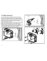


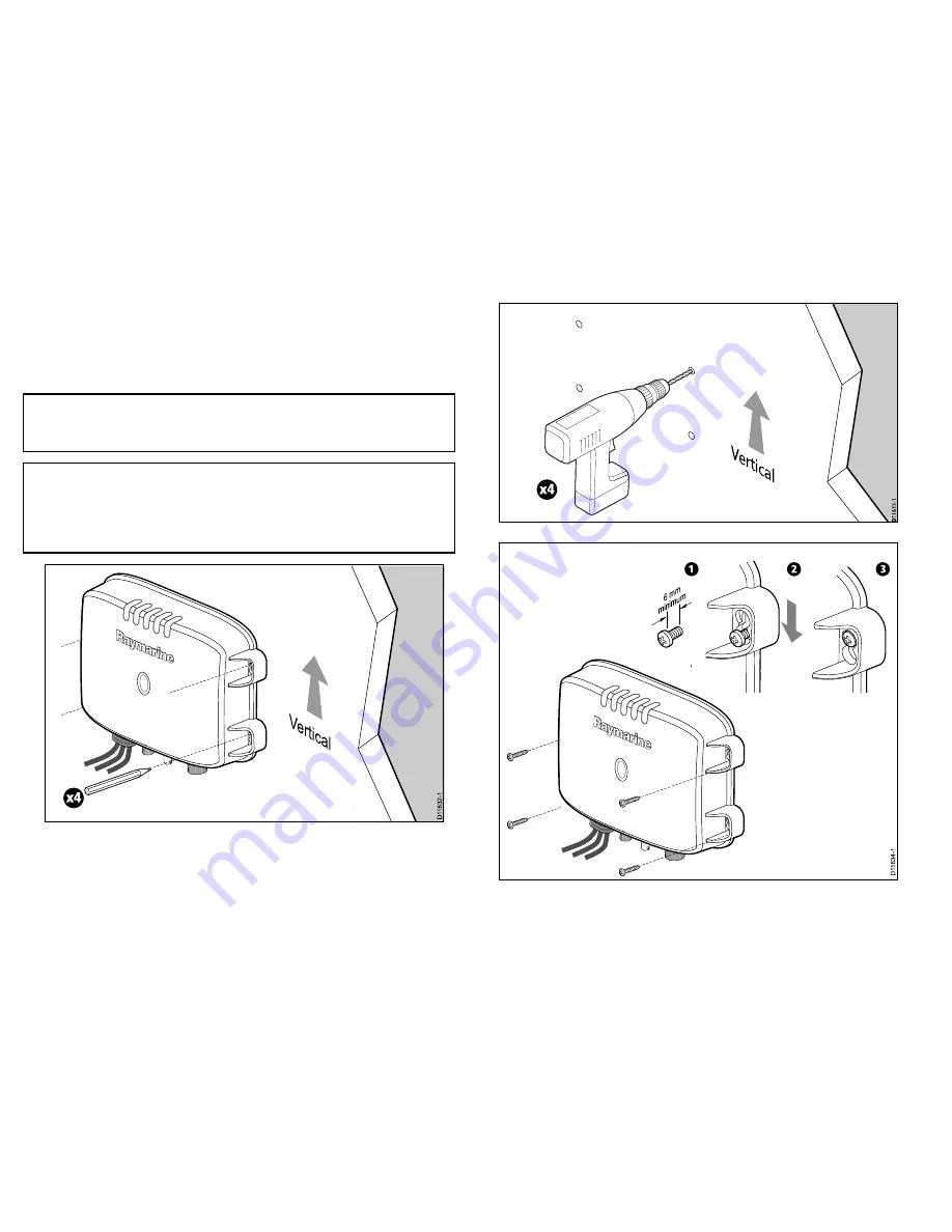
4.1 Fitting transceiver
Ensure that the intended installation site meets the conditions
described under Site requirements, mark and drill the mounting
holes, then fit the transceiver as shown in the following illustrations.
Note:
This procedure shows how to mount the transceiver
vertically, which is the recommended method. However, you may
mount it horizontally if necessary.
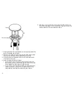
Note:
If you are fitting the transceiver to fiberglass that has
a gelcoat surface, overdrill the surface to prevent the gelcoat
from damage when securing the screws. Before drilling the pilot
holes, hand drill the marked locations with an oversized bit and
countersink to approximately 9.5 mm (3/8 in) diameter.
1.
Vertic
al
x4
D
1
1632-1
2.
Verti
cal
x4
D11633-1
3.
1
2
3
6 mm
minimum
D1
1
634-1
28
Содержание AIS500
Страница 1: ...AIS500 Transceiver Installation instructions AUTOMATIC IDENTIFICATION SYSTEM...
Страница 2: ......
Страница 4: ......
Страница 6: ...6...
Страница 16: ...16...
Страница 34: ...D11649 1 Red Black Power supply Power supply Connect to 12 V dc or 24 V dc 34...
Страница 42: ...42...
Страница 46: ...46...
Страница 47: ......
Страница 48: ...www raymarine com...


