Raymarine AIS500 Скачать руководство пользователя страница 24

3.1 Cable types and length

It is important to use cables of the appropriate type and length

• Unless otherwise stated use only standard cables of the correct

type, supplied by Raymarine.

• Ensure that any non-Raymarine cables are of the correct quality

and gauge. For example, longer power cable runs may require
larger wire gauges to minimize voltage drop along the run.

3.2 Routing cables

Cables must be routed correctly, to maximize performance and
prolong cable life.

• Do NOT bend cables excessively. Wherever possible, ensure a

minimum bend radius of 100 mm.

Minimum bend of cable
100 mm (4 in) radius

Minimum bend
200 mm (8 in)
diameter

• Protect all cables from physical damage and exposure to heat.

Use trunking or conduit where possible. Do NOT run cables
through bilges or doorways, or close to moving or hot objects.

• Secure cables in place using tie-wraps or lacing twine. Coil any

extra cable and tie it out of the way.

• Where a cable passes through an exposed bulkhead or deckhead,

use a suitable watertight feed-through.

• Do NOT run cables near to engines or fluorescent lights.

Always route data cables as far away as possible from:

• other equipment and cables,

• high current carrying ac and dc power lines,

• antennae.

24

Содержание AIS500

Страница 1: ...AIS500 Transceiver Installation instructions AUTOMATIC IDENTIFICATION SYSTEM...

Страница 2: ......

Страница 3: ...utoadapt Auto GST AutoSeastate AutoTrim Bidata G Series HDFI LifeTag Marine Intelligence Maxiview On Board Raychart Raynav Raypilot RayTalk Raystar ST40 ST60 Seaclutter Smart Route Tridata UniControl...

Страница 4: ......

Страница 5: ...ter 3 Cables connections 23 3 1 Cable types and length 24 3 2 Routing cables 24 3 3 Transceiver connections 25 3 4 Cable shielding 26 Chapter 4 Installation procedures 27 4 1 Fitting transceiver 28 4...

Страница 6: ...6...

Страница 7: ...d to navigation and must never be used in preference to sound navigational judgment Only official government charts and notices to mariners contain all the current information needed for safe navigati...

Страница 8: ...To register your AIS500 transceiver ownership please take a few minutes to fill out the warranty registration card found in the box or visit www raymarine com and register on line It is important that...

Страница 9: ...nsceivers comply with the Federal Communications Commission FCC and Industry Canada requirements that regulate marine AIS and VHF radio usage for the US and Canada respectively Marine AIS users in the...

Страница 10: ...0 Output Power 2 Watts Modulation GMSK Frequency Range 156 025 to 162 025 MHz Maritime Mobile Service Identity MMSI A nine digit Maritime Mobile Service Identity MMSI number is required to operate the...

Страница 11: ...g located where it will be away from people located at least 1 5 meters 5 feet from the radio s main unit Requirements for areas outside of USA Canada Maritime Mobile Service Identity MMSI A nine digi...

Страница 12: ...ands Denmark Norway Estonia Poland Finland Portugal France Romania Germany Slovakia Greece Slovenia Hungary Spain Iceland Sweden Ireland Switzerland Italy Turkey Latvia United Kingdom Declaration of C...

Страница 13: ...eives messages from and transmits messages to vessels carrying Class A or Class B transceivers Class A Transceivers Class A AIS transceivers transmit and receive AIS signals AIS transceivers are curre...

Страница 14: ...st when data has been amended or upon request or by default every 6 minutes The reporting rates for dynamic information depend on speed and course change and are given in the following tables Note The...

Страница 15: ...her AIS sources Source Reporting rate Search and Rescue SAR aircraft 10 seconds Aids to navigation 3 minutes AIS base station 10 seconds or 3 33 seconds depending on operating parameters Introduction...

Страница 16: ...16...

Страница 17: ...r 2 Planning the installation Chapter contents 2 1 EMC installation guidelines on page 18 2 2 Parts supplied on page 19 2 3 Tools required on page 19 2 4 Basic system on page 20 Planning the installat...

Страница 18: ...to prevent erratic behavior and data loss which can occur if the engine start does not have a separate battery Raymarine specified cables are used Cables are not cut or extended unless doing so is det...

Страница 19: ...Installation instructions Warranty document CDROM AIS 500 AIS500 Transceiver Installation instructions AUTOMATIC IDENTIFI CATION SYSTEM D11623 1 Mounting studs x 2 Thumb nuts x 2 2 3 Tools required En...

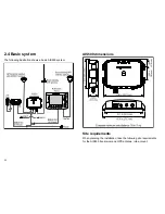
Страница 20: ...GPS antenna typical GPS antenna supplied withAIS500 Tranceiver SeaTalk D11625 1 VHF radio SeaTalkng Power in RS232 0 0 AIS 500 RF AIS500 dimensions 9 51 in 241 6 mm 10 76 in 273 3 mm 7 37 in 187 2 mm...

Страница 21: ...of your VHF set If the level of degradation is unacceptable we recommend you use separate VHF antennae for the AIS500 and the VHF set The loss values for the inbuilt splitter are given in the Specific...

Страница 22: ...h the multi function displays are connected via SeaTalkng Before connecting to SeaTalkng refer to the SeaTalkng Reference Manual and ensure that with this product connected the maximum permitted Load...

Страница 23: ...pter 3 Cables connections Chapter contents 3 1 Cable types and length on page 24 3 2 Routing cables on page 24 3 3 Transceiver connections on page 25 3 4 Cable shielding on page 26 Cables connections...

Страница 24: ...r possible ensure a minimum bend radius of 100 mm Minimum bend of cable 100 mm 4 in radius Minimum bend 200 mm 8 in diameter Protect all cables from physical damage and exposure to heat Use trunking o...

Страница 25: ...d be used for the AIS500 transceiver and the VHF radio In this case the supplied 1 m RF cable is not used and the VHF RADIO connector on the AIS500 transceiver remains unconnected Note that when the A...

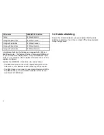
Страница 26: ...only one NMEA0183 port exists on your equipment the multiplexer eliminates the need for a separate multiplexer Typically the NMEA0183 connections are used as follows The 4800 baud wires connect to the...

Страница 27: ...Chapter 4 Installation procedures Chapter contents 4 1 Fitting transceiver on page 28 4 2 Fitting GPS antenna on page 29 4 3 Connecting up on page 31 Installation procedures 27...

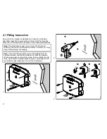
Страница 28: ...ertically which is the recommended method However you may mount it horizontally if necessary Note If you are fitting the transceiver to fiberglass that has a gelcoat surface overdrill the surface to p...

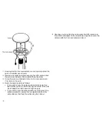
Страница 29: ...ed from the side of the receiver i e above the mounting surface remove the two plastic tabs 1 obstructing the cable channel If you do not remove these tabs before using the cable channel you could dam...

Страница 30: ...ute the antenna cable as follows i If you want to route the antenna cable directly down from the antenna option A feed it through the center of the pole mount adaptor and then down through the pole ii...

Страница 31: ...lent Mode and an alarm message will be generated You must acknowledge all alarm messages The transceiver will not transmit but will still receive Connecting to VHF Ensure power to the ship s VHF set i...

Страница 32: ...onnected to a SeaTalkng system connect the AIS500 transceiver 38400 baud NMEA0183 bus to the boat s 38400 baud NMEA0183 system as follows 1 Identify the 38400 baud NMEA0183 wires from the AIS500 trans...

Страница 33: ...for each power circuit D1 1637 1 VE bar Circuit breaker Fuse Fuse VE bar Where possible connect individual items of equipment to individual circuit breakers Where this not possible use individual in...

Страница 34: ...D11649 1 Red Black Power supply Power supply Connect to 12 V dc or 24 V dc 34...

Страница 35: ...er 5 Post installation procedures Chapter contents 5 1 Switching on on page 36 5 2 Configuration on page 36 5 3 Checking for interference on page 37 5 4 Using AIS on page 38 Post installation procedur...

Страница 36: ...e or other erroneous data Configuration requirement After installation and successful switch on the AIS500 transceiver must be configured for optimum performance aboard the vessel The person configuri...

Страница 37: ...User Guide 5 3 Checking for interference Post installation check If you have installed any system aboard a boat or made other changes to the boat s electronic systems radar VHF radio etc you need to...

Страница 38: ...5 4 Using AIS The exact method of using AIS depends on which type of Raymarine multi function display MFD you are using Refer to the handbook for your MFD for information on using AIS 38...

Страница 39: ...Chapter 6 Diagnostics Chapter contents 6 1 Status indication on page 40 6 2 Troubleshooting on page 41 Diagnostics 39...

Страница 40: ...tes When the first position report has been transmitted the STATUS indicator goes to GREEN This condition remains all the time the AIS500 transceiver is operating normally A summary of STATUS indicato...

Страница 41: ...ON Ensure displayed target types are set to ALL No AIS data Check the NMEA output from the multi function displays to the AIS500 input and ensure The wires are correctly connected The baud rate is 38...

Страница 42: ...42...

Страница 43: ...Chapter 7 Specifications Chapter contents 7 1 General on page 44 7 2 Transceiver on page 44 7 3 GPS Receiver on page 45 Specifications 43...

Страница 44: ...g screws Connectors VHF antenna SO 239 VHF In BNC GPS In TNC PC RS232 9 Way D Type NMEA0183 HS stripped wires NMEA0183 LS stripped wires Power stripped wires SeaTalkng proprietary Raymarine connector...

Страница 45: ...7 3 GPS Receiver Receiver channels 16 Receiver sensitivity Acquisition 140 dBm Tracking 150 dBm Nominal Time to First Fix 34 seconds Specifications 45...

Страница 46: ...46...

Страница 47: ......

Страница 48: ...www raymarine com...

Отзывы: