background image

RG27/35/37 Operation • Service • Maintenance 

800.392.2686

23

Safety

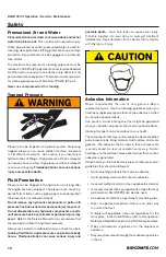
Precautions for Welding on FRAME 

with ENGINE/MACHINE Electronic 

Control Unit (ECU)

Important: ALWAYS disconnect Electronic Control Unit (ECU) 
connectors and engine control system-to-machine ground 
before welding on engine or machine.
High currents or electrostatic discharge in electronic 
components from welding may cause permanent damage

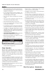
Safety Decals

The safety decals located on this machine contain useful 
and important information which will help you to operate 
your machine safely. The complete decal kit and location of 
each decal is given in the “Parts” manual. For your protection, 
familiarize yourself with each label until you completely 
understand the warning intended. Do not violate any such 
warnings!
Keep all decals in place and in good condition:

•  Use soap and water to keep decals clean. DO NOT 

use mineral spirits, abrasive cleaners or other similar 

cleaners which will damage the decals.

•  Replace any damaged or missing decals. Before 

attaching decals, the surface temperature of the metal 

must be at least 40 degrees. The metal should also be 

clean and dry before attaching the decal.

•  If a machine component to which a decal is attached is 

replaced, be sure to replace the decal as well.

•  Replacement decals may be purchased from Rayco Mfg 

or your Rayco dealer.

LOCK-Out / Tag-Out Guidelines

Always practice lock out tag out procedures when working 
on this machine.
Locking and tagging out equipment safeguards those working 
on the equipment from being injured by its unexpected 
energized or releasing stored energy. This section summarizes 
the applicable requirements for lockout/ tag out procedures, 
and its intent to comply with OSHA regulations.

Lock Out Procedure

•  All affected persons are to be notified that the equipment 

will be off and locked out.

•  All energy sources for the equipment should be identified.
•  The equipment shall be shut off or otherwise deenergized, 

being careful to de-energize all energy sources. This 

includes all valves, switches, breakers, or other controls 

that supplies energy to the equipment. In case of 

mechanical energy, a block may be used to stop the 

release of stored energy.

•  A lock is to be placed on each energy source disconnect 

or energy release block.

  1. The lock is to be placed directly on the equipment if 

provided with an integral locking device.

  2. If there is no integral lockout device on the equipment, 

securely attach an independently manufactured lockout 

device on the equipment and then place the lock on the 

lockout device.

  3. If none of the above are possible, use the tag out 

procedure.

•  A tag to be secured to the lock indicating that the 

equipment is not to be energized and who owns the lock.

•  It should be safely tested and verified that the lockout 

does prevent the release of energy.

Tag Out Procedure

•  This procedure is to be used only if it is not reasonable 

to use the lockout procedure.

•  All affected persons are to be notified that the equipment 

will be shut off and tagged out.

•  All energy sources for the equipment should be identified.
•  The equipment shall be shut off or otherwise de-

energized, being careful to de-energize all energy 

sources. This includes all valves, switches, breakers, or 

other controls that supplies energy to the equipment. 

incase of mechanical energy, a block may be used to 

stop the release of stored energy.

•  Securely place a tag on each energy source disconnect 

or energy release block.

Removal Procedure

•  Lockout/tag out equipment must be removed by the 

worker who placed it.

•  Before the removal of a lockout/tag out the following 

must be completed:

  1. Removal of all non essential items.
  2. Check to see that all workers and bystanders are 

located in a safe position.

  3. Inform all affected personnel.
•  If a worker who applied the lockout/tag out is not present, 

and his supervisor deems it necessary to energize the 

equipment, the following must be done by the supervisor.

  1. Make all reasonable effort to contact the worker who 

placed the tag.

  2. Determine the purpose of the lockout/tag out, and 

whether it is safe to operate the equipment in its current 

condition.

  3. Remove all non essential items.

Содержание Super Jr RG27

Страница 1: ...RG27 RG35 RG37 Super Jr OPERATOR SERVICE MAINTENANCE MANUAL RAYCO MANUFACTURING 2017 ALL RIGHTS RESERVED PRINTED IN USA INDEX OSMRG27 35 37 17 ...

Страница 2: ...dunderstandallinstructionsbefore attempting to operate this machine This manual should be readily available for reference at all times Additional copies of this manual may be purchased from Rayco This Rayco machine was designed and manufactured by RaycoManufacturing Inc Wooster Ohio Duetocontinuous improvements Rayco reserves the right to make changes in engineering design and specifications or di...

Страница 3: ...RG27 35 37 Operation Service Maintenance 800 392 2686 3 Table of Contents TABLE OF CONTENTS Forward 4 Safety 8 Operation 24 Maintenance 32 Specifications 44 Warranty 55 ...

Страница 4: ...ice Operation The operation section is a reference for the new operator and a refresher for the experienced operator This section includesadiscussionofgauges switches machinecontrols attachment controls transportation and towing information Photographs and illustrations guide the operator through correct procedures of checking starting operating and stopping the machine Operating techniques outlin...

Страница 5: ...cal regulations for the disposal of liquids Use all cleaning solutions with care Report all necessary repairs Do not allow unauthorized personnel on the equipment Unless you are instructed otherwise perform maintenance with the equipment in the servicing position Refer to Operation and Maintenance Manual for the procedure for placing the equipment in the servicing position When you perform mainten...

Страница 6: ...he number of produced 01 Two digit month 01 Jan 02 Feb etc 17 Two digit year 17 2017 18 2018 etc It is attached to the machine at the location shown For ready reference record it in the boxes provided on the inside front cover of this manual For reference on communication regarding the engine record its model and serial numbers also in the boxes provided on the inside front cover of this manual Se...

Страница 7: ...ation Identification Numbers Model Number Serial Number Machine Engine Implement Implement Dealer Information Name Address Dealer Contact Phone Number Hours Sales Parts Service Serial number is located as shown Use the below table to record identification numbers and dealer information ...

Страница 8: ...not specifically recommended by Rayco you must use it only if you have accurately evaluated it and found that it threatens no one s safety You should also ensure that the product will not be damaged or made unsafe by the operation lubrication maintenance or repair procedures that you choose The procedures described in this Safety section may not be fully explained here but a more complete explanat...

Страница 9: ...ANSI Z89 1 and DO NOT wear under chin strapping while operating or within the operation area of the Horizontal Grinder Eyeprotection mustconformtoANSIZ87 1andbethewrap aroundstyle Alwaysweartheeyeprotectionwhenoperating or working within the operational area of the machine Hearing Protection Plug type ear protection or full ear coverage devices muff type shall be worn at all times when operating o...

Страница 10: ...aulic pressure Always use a board or cardboard when you check for a leak Leaking fluid that is under pressure can penetrate body tissue Fluid penetration can cause serious injury and possible death A pin hole leak can cause sever injury If fluid is injected into your skin you must get treatment immediately Seek treatment from a doctor that is familiar with this type of injury Asbestos Information ...

Страница 11: ...you are instructed otherwise never attempt adjustments while the machine is moving or while the engine is running Never jump across the starter solenoid terminals in order to starttheengine Unexpectedmachinemovementcouldresult Wheneverthereareequipmentcontrollinkages theclearance in the linkage area will change with the movement of the equipment or the machine Stay clear of areas that may have a s...

Страница 12: ...t the skin the eyes or the mouth Oils Hot oil and hot components can cause personal injury Do not allow hot oil to contact the skin Also do not allow hot components to contact the skin Remove the hydraulic tank filler cap only after the engine has been stopped The filler cap must be cool enough to touch with a bare hand Follow the standard procedure in this manual in order to remove the hydraulic ...

Страница 13: ...r Inspect the fire extinguisher and service the fire extinguisher regularly Obey the recommendations on the instruction plate Fire Extinguisher Location Makesurethatafireextinguisherisonthemachine Makesure that you are familiar with the operation of the fire extinguisher Inspect the fire extinguisher and service the fire extinguisher Obey the recommendations on the instruction plate Mount the fire...

Страница 14: ...erial extends above the cab top guards and front guards should be used Additional guards may be required for specific applications or work tools The Operation and Maintenance Manual for your machine or your work tool will provide specific requirements for the guards Consult your Rayco dealer for additional information Precautions for Welding on FRAME with ENGINE MACHINE Electronic Control Unit ECU...

Страница 15: ...area check for proper operation of all controls and all protective devices Do not allow riders on the machine Note any needed repairs during machine operation Report any needed repairs to certified service technician UseonlyRaycoApprovedWorkToolsonthismachine Obey all the lift restrictions Refer to Operation and Maintenance Manual RaycoApprovedWorkTools fortheapprovedwork tools and the lift restri...

Страница 16: ... of inertia tend to make the machine less stable Roughness of terrain or surface The machine may be less stable with uneven terrain Direction of travel Avoid operation the machine across the slope When possible operate the machine up the slopes and operate the machine down the slopes Place the heaviest end of the machine uphill when you are working on an incline Mounted equipment Balance of the ma...

Страница 17: ...eenergized being careful to de energize all energy sources This includes all valves switches breakers or other controls that supplies energy to the equipment In case of mechanical energy a block may be used to stop the release of stored energy A lock is to be placed on each energy source disconnect or energy release block 1 The lock is to be placed directly on the equipment if provided with an int...

Страница 18: ...ke sure the tow vehicle is of adequate size and has the towing capacity to safely tow the combined weight of trailer machine Never tow a machine while it is running Towing will affect handling allow for extra stopping distances Refer to U Haul s Safe Trailering Driver EducationProgramthatisavailableatthiswebsite http www uhaul com guide index aspx equipment towing autotransport Make sure the towin...

Страница 19: ...ess the tongue jack is fully raised off the ground NEVER allow passengers to ride on the trailer No open or soft top sport utility vehicle is allowed to tow a trailer because in the event of a crash these vehicles offer less collision and ejection protection Your Tow Vehicle Refer to the owner s manual decal instructions or an authorized automotive dealer for any specific handling characteristics ...

Страница 20: ... with brakes have a third chain called the emergency brake chain This chain applies the brakes automatically in the unlikely event of a separation of the trailer from the tow vehicle Attach this chain as close to the vehicle center as possible to the tow vehicle permanent hitch frame or structure or to the bumper brackets Twist chain to take up most of the slack and secure Some slack is necessary ...

Страница 21: ... Towing Checklist Before Towing Towing hitch and hitch ball are tight Coupler is tight Safety chains tire straps and security chains are properly attached and secure All lights are connected and working Check all tires for correct pressure Load vehicle in tow heavier end engine end toward the front of the trailer Ramps securely stored and latched Tongue jack is fully raised Before Driving Fasten s...

Страница 22: ...ations smoothly a Steer b Brake c Accelerate d Shift the gears 6 Move the attachments smoothly 7 Adjust the machine speed and the route in order to minimize the vibration level a Drive around obstacles and rough terrain b Slow down when it is necessary to go over rough terrain 8 Minimize vibrations for a long work cycle or a long travel distance a Haul the machines between workplaces Guards Operat...

Страница 23: ...e all energy sources This includes all valves switches breakers or other controls that supplies energy to the equipment In case of mechanical energy a block may be used to stop the release of stored energy A lock is to be placed on each energy source disconnect or energy release block 1 The lock is to be placed directly on the equipment if provided with an integral locking device 2 If there is no ...

Страница 24: ...ust be certain that no one will be endangered While you operate the machine and the work tool slowly in an open area check for proper operation of all controls and all protective devices Do not allow riders on the machine Note any needed repairs during machine operation Report any needed repairs to certified service technician UseonlyRaycoApprovedWorkToolsonthismachine Obey all the lift restrictio...

Страница 25: ...hat all personnel are out of the work area While you are performing any maintenance any testing or any adjustments to the machine stay clear of the follow ing areas cutting edges pinching surfaces and crushing surfaces Equipment Lowering with Engine Stopped Before lowering any equipment with the engine stopped clear the area around the equipment of all personnel The procedure to use will vary with...

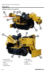
Страница 26: ...ice Maintenance 26 Getting to know your machine Operation 1 Operator Panel 2 Fuel Hydraulic Tanks 3 Blade 4 Steer Axle 5 Safety Curtains 6 Cutter Wheel 7 Cutter Boom Belt 8 Engine 9 Swing Out Arm 1 2 3 4 5 5 5 6 7 8 9 11 10 12 ...

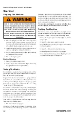
Страница 27: ... Run the engine for about two minutes while intermit tent ly holding the cutting wheel raise lever in the RAISE position 3 Movetheenginethrottletothemax i mumenginespeed Run theengineforanaddition altwominuteswhilein ter mit tent ly hold ingthecuttingwheelraiseleverintheRAISEposition This will allow the oil to reach relief pres sure which causes it to warm up more rapidly 4 Cycle all the controls ...

Страница 28: ...Down RG37Only 10 Cutter Wheel On Off Pull the switch up after the engine is running and the safety tether is lowered in its correct position NOTE The cutter wheel will not engage if the safety tether is not in its proper location NOTICE The control levers will re center themselves in a neutral position when released No movement should occur if you observe any movement when controls are in nuetral ...

Страница 29: ... to drain back into the gun 2 Disconnect the gun from the brake release fitting using the wrench 3 You may now empty the remaining fluid back into the plastic bottle from the gun 4 Reconnect hydraulic hose the brake release fitting you removed earlier in step 3 5 Tighten the needle valve screw loosened in step 2 6 Iftheproperrepairshavebeenmadetothemachine you may follow the starting procedure out...

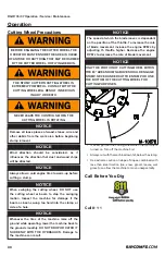
Страница 30: ...fore cutting a stump NOTICE When swinging the cutting wheel DO NOT use the cutting wheel or boom to stop the swinging motion Inspect the machine for damage if the boom as been swung too hard into the stump or side of a hole NOTICE Whenever the tires of the machine raise off the ground while operating lower the ma chine back to the ground smoothly DO NOT DROP OR CATCH IT SUDDENLY WITH THE HYDRAULIC...

Страница 31: ...pproximately 2 75 deep bite After the first bite is taken lower the cutting wheel about 2 while is off to the side and swing the cutting wheel across for another bite Continuerepeatingthisprocedureuntilalloftheamount of stump in the path of the downward swing of the cutting wheel is gone 4 Cut another level of the stump Raise the cutting wheel above the stump once again and starting with the cutti...

Страница 32: ...r visibly creep when it is not being moved The machine can be tested on any slope but the simplest inspection can be done when unloading or loading the machine onto its trailer or into a pickup truck When the drive wheels are on the ramps bring the machine to a halt and observe the drive wheels The wheels should not turn at all No creep should be evident If the machine can be observed to be creepi...

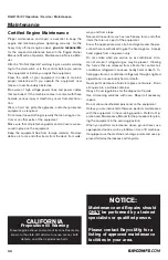
Страница 33: ...gine in not used for a long period of time run it for about 5 minutes under no load every 2 3 months to keep it free from rust If the engine is stored without any running moisture in the air may condense into dew over the sliding parts of the engine resulting in rust there 6 Ifyouforgettoruntheengineforlongerthan5 6months applyenoughengineoiltothevalveguideandvalvestem seal and make sure the valve...

Страница 34: ...nt Know the appropriate work site hand signals and the per sonnel that are authorized to give the hand signals Accept hand signals from one person only Do not smoke when you service an air conditioner Also do not smoke if refrigerant gas may be present Inhaling the fumes that are released from a flame that contact air conditioner refrigerant can cause bodily harm or death In haling gas from air co...

Страница 35: ...RG27 35 37 Operation Service Maintenance 800 392 2686 35 Maintenance Maintenance Log Date of Service Machine Hours Description of Service Maintenance Notes ...

Страница 36: ...e Valve Clearance Check Engine Oil Filter Change Every 250 Hrs Maintenance Interval Hydraulic Oil Filter Change Self Propel Wheel Bearings Service Engine Valve Clearance Check Battery Check Engine Fuel Filter Change Every 500 Hrs or 1 Year Maintenance Interval Hydraulic Oil Filter Change Spark Plugs Change Every 50 Hrs Maintenance Interval Slewing Ring Grease SOA Bushings Grease Pivot Bushings Gre...

Страница 37: ...ter cleaning blow the oil cooler dry with compressed air that does not exceed 40 psi 275 kPa Engine Oil Filter Change Follow directions in the Engine Operator Manual 1 With engine OFF but still warm remove the oil drain plug 2 and drain oil into appropriate container When finished reinstall the drain plug 2 Remove the oil filter 3 by turning counterclockwise as shown 3 Apply a light oil film on th...

Страница 38: ...edhydrau licoil see LubricationandFluidSpecifications whichshouldbe passed through a 10 micron nom i nal non bypass filter prior to entering the reservoir Never reuse fluid 3 Crank the engine using the starter for a short period of time This allows the system to begin filling with fluid Start the engine and run at the lowest possible speed Shut down the engine within 40 seconds if the pump or moto...

Страница 39: ...ditions Brake Test This machine is required to have a daily inspection of the ground drivebrake Thischeckshouldbedonebytheoperator every day before using the machine Theground drivebrakeonthismachineisaspring activated hydraulically releasedunit Thismeansthatanytimetheunitis not being moved with hydraulic pressure the spring applied brake should engage The machine should never visibly creep when i...

Страница 40: ...l Cylinder Rods Apply Oil Apply SAE 30 engine oil and spread evenly over the exposed portion of the rod 1 on both the left and right cylinders Battery Check Adjust Electrolyte Level 1 Raise the hood 2 Remove each cap carefully by prying with a screwdriver 3 Electrolyte level should be 1 4 to 1 2 above the metal plates just touching the bottom of the plastic fill neck Add distilled water as needed ...

Страница 41: ...grease If abnormal wear or other damage seems present replace bearings immediately Worn or frozen bearings can damage the drive components Slewing Ring Lubricate 3 4 shots of grease into the grease fitting on the slewing ring 3 located under the boom asm There is a zerk on either side of the slewing ring Note Driedgreasecanplugholes ifgreasedoesnotooze out of holes use very small drill bit to loos...

Страница 42: ...er 7 Self propel Axle Flange Bearings Lubricate 3 4 shots of grease into the grease fittings 4 on both outer axle flange bearings Cutting Wheel Lubricate Lubricate the two fittings 5 one on each side until you can visually see old grease being purged out of the side of the bearing Cutting Wheel PolyChain Check Adjust Tension Using a belt gauge check the PolyChain tension by depressing the PolyChai...

Страница 43: ...Gage The belt tension should be set to deflect 1 2 using 18 20 lbs force with a belt plunger gage If tension is acceptable proceed to step 7 3 Loosenthefourenginemountingbolts 10 whichsecure the engine to the cutting boom 4 Loosen the jam nut 11 on the engine adjusting nut Turn the engine adjusting nut 12 clockwise to tighten the belts to the proper tension 5 Check the belt tension again If it is ...

Страница 44: ...y solution The teeth are spaced to provide a maximum depth of cut for the number of teeth on the wheel Some of the wheels available today use a large quantity of teeth to get the same depth of cut that a Rayco wheel will achieve with half the teeth While the individual tooth cost may be less the overall costs are more Additionally having too many teeth in the stump at any one time can lead to aggr...

Страница 45: ... tooth for comparison 2 Discard any tooth that has lost more than 1 8 of original bite whether lost through usage or grinding 3 Grind off a minimal amount from the end just enough to restore the original taper and radius on the end The end of the cemented carbide tip and the end of the steel shank should be flush after grinding NOTICE Read all of the following instructions before beginning to chan...

Страница 46: ... be easier to take the PTO off to make adjustments A 015 022 feeler gauge and a 9 16in Open end box wrench is all that is needed There are three inspection slots on the brake shroud Place the feeler gauge in the slot between the armature and rotor Slowly tighten down the brake nut until there is contact with the feeler gauge Once gap is set rotate rotor and armature check gap withfeelergaugeandmak...

Страница 47: ...RG27 35 37 Operation Service Maintenance 800 392 2686 47 Maintenance Notes ...

Страница 48: ...asures Lack of fuel Check the fuel tank and refill with fuel if necessary Also check the fuel system for air or leaks Bad nozzle If necessary replace with a new nozzle Moving parts are overheated due to shortage of lubrication oil or improper lubrication Check amount of engine oil with oil level gauge Check lubricating oil system At every 2 times of oil change the oil filter cartridge should be re...

Страница 49: ...the filter base gasket When engine overheats Cause Countermeasures Engine oil insufficient Check oil level Refill as necessary Fan belt broken or elongated Change belt or adjust belt tension Coolant insuf ficient Replenish coolant Excessive concentration of antifreeze Add water only or change to coolant with the specified mixing ratio Radiator net or fin clogged with dust Carefully clean net or fi...

Страница 50: ...RG27 35 37 Operation Service Maintenance 50 Wiring Schematic ...

Страница 51: ...RG27 35 37 Operation Service Maintenance 800 392 2686 51 Wiring Schematic ...

Страница 52: ...ion Service Maintenance 52 Hydraulic Schematic RG27 802591 D OVER CENTER VALVE K FITTINGS LIFT CYLINDER N FITTINGS AND HOSES 8 AND 10 ARE FROM HOSE KIT 802591 RF T T P P RG27 BLADE OPTION 802597 HYD KIT STANDARD ON RG35 ...

Страница 53: ...HYDRAULIC FILTER ASM E 1 760115 PUMP HYDRAULIC F 1 738008 VALVE SWING CONTROL G 1 801152 DUAL COUNTER BALANCE W PILOT PORT H 1 802526 MOTOR DRIVE BRAKE PARKER J 1 738011 VALVE LOCK SWING K 1 1200015 OVER CENTER VALVE L 1 801738 CYLINDER STEER M 1 29193 CYLINDER SWING N 1 802488 CYLINDER LIFT P 1 801256 VALVE SPOOL Q 1 802228 VALVE 1 SPOOL MOTOR ITEM QTY PART DESCRIPTION ...

Страница 54: ...RG27 35 37 Operation Service Maintenance 54 Hydraulic Schematic RG37 802846 RF T T P P ...

Страница 55: ...ILTER ASM E 1 764215 PUMP TANDEM 31 31 F 1 738008 VALVE SWING CONTROL G 1 801152 DUAL COUNTER BALANCE W PILOT PORT H 1 802526 MOTOR DRIVE BRAKE PARKER J 1 738011 VALVE LOCK SWING K 1 1200015 OVER CENTER VALVE L 1 801738 CYLINDER STEER M 1 29193 CYLINDER SWING N 1 802488 CYLINDER LIFT P 3 1200105 VALVE SPOOL Q 1 802228 VALVE 1 SPOOL MOTOR R 1 24237 CYLINDER BLADE ITEM QTY PART DESCRIPTION ...

Страница 56: ...RG27 35 37 Operation Service Maintenance 56 Specifications SERVICING TAPER BUSHINGS ...

Страница 57: ...bricants Before attempting to start the engine make sure that the oil in the engine the transmission and the hydraulic system are fluid enough to flow Check the oil by removing the dipsticks If the oil will drip from the dipstick then the oil is fluid enough to start the engine Do not use oil that has been diluted with kerosene Kerosene will evaporate in the engine If the viscosity of the oil is c...

Страница 58: ... C 46 cSt 40 C Pour 30 C 22 F Mobil DTE 15M Viscosity 7 8 cSt 100 C 46 cSt 40 C Pour 36 C 33 F If choosing an oil other than those recommended above the following specifications should be used Kinematic Viscosity 6 7 cSt 100 C 46 cSt 40 C Pour point 30 C 22 F or colder Viscosity stabilizers excellent resistance to viscosity breakdown shear Anti wear Anti foam formulation for use in all pump types ...

Страница 59: ...e Free Diluted P N 227034 227045 with bitterant 34 F 50 mix 62 F 60 mix Coolant Maintenance Maintain freeze point between 15 F and 62 F A 50 mixture has a freeze point of 34 F refer to freeze point above Use commercially available test strips for both nitrate and molybdate Maintain nitrate levels between 800ppm and 2300ppm Check levels of nitrate and molybdate every 250 hrs Add SCA s based upon th...

Страница 60: ...lve Spring Centered Series Hose Capacity 3000 PSI Working Pressure Swing Cylinder Minimum 3 Bore 6 Stroke 1 1 4 Rod Minimum Lift Cylinder Minimum 2 5 Bore 8 Stroke 1 1 4 Rod Hydraulic Wheel Drive Motor 10 4 cu In rev Drive Chain 50R Series Minimum Fittings O ring Required Cutting Wheel Wheel Diameter 17 25 Maximum Wheel Thickness 1 Minimum Cutting Wheel Bearings 1 5 Pillow Block Minimum RPM 1170 A...

Страница 61: ...ll Flow Oil Type Tellus T46 Valve Spring Centered Series Hose Capacity 3000 PSI Working Pressure Swing Cylinder Minimum 3 Bore 6 Stroke 1 1 4 Rod Minimum Lift Cylinder Minimum 2 5 Bore 8 Stroke 1 1 4 Rod Hydraulic Wheel Drive Motor 10 4 cu In rev Drive Chain 50R Series Minimum Fittings O ring Required Cutting Wheel Wheel Diameter 17 25 Maximum Wheel Thickness 1 Minimum Cutting Wheel Bearings 1 5 P...

Страница 62: ... Oil Type Tellus T46 Valve Spring Centered Series Hose Capacity 3000 PSI Working Pressure Swing Cylinder Minimum 3 Bore 6 Stroke 1 1 4 Rod Minimum Lift Cylinder Minimum 2 5 Bore 8 Stroke 1 1 4 Rod Hydraulic Wheel Drive Motor 10 4 cu In rev Drive Chain 50R Series Minimum Fittings O ring Required Cutting Wheel Wheel Diameter 17 25 Maximum Wheel Thickness 1 Minimum Cutting Wheel Bearings 1 5 Pillow B...

Страница 63: ...RG27 35 37 Operation Service Maintenance 800 392 2686 63 ...

Страница 64: ...dicator 761909 Outer Air Filter Cartridge 780270 Inner Air Filter Cartridge 750202 Service indicator 761600 Fuel Cap 801682 Engine Key 755553 Parts Manual PMRG27 35 37 Operation Manual OBRG27 35 37 Operation Service Manual OSMRG27 35 37 CUTTER WHEEL TEETH Straight Counter bore 3144C Straight Threaded 3144T Angle Out Counter bore 2933C Angle Out Threaded 2933T refer to page 33 for more details ...

Страница 65: ...he product to and from the place at which warranty work is performed 3 Any product that has been altered or modified in ways not approved by Rayco 4 Depreciation or damage caused by normal wear lack of reasonable and proper maintenance failure to follow operating instructions misuse lack of proper protection during storage or accident D Unapproved Service Modification Rayco is relieved of its obli...

Страница 66: ...hink Safe We care about your safety When operating your RAYCO machinery always wear an ap proved helmet complete with ear muffs face shield and the proper eye wear Never operate under the influence of alcohol or drugs Know your RAYCO read and understand your owner s manual cover to cover RAYCO Manufacturing Inc retains the right to make changes in design and specifications engineering add or remov...

Отзывы: