


8
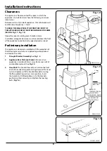
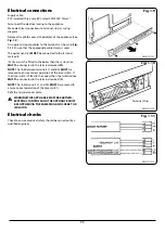
Clearances
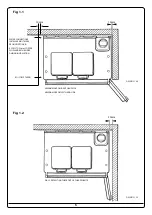
The appliance is floor mounted. The space in which the
appliance is to be fitted must have the following minimum
dimensions:-
Between wall and LH side of appliance - 10mm Between wall
and RH side of appliance - 10mm*
*SHOULD THE WALL PROJECT BEYOND THE FRONT OF
THE APPLIANCE, WHEN IT MUST BE INCREASED TO 50MM
(SEE FIG. Fig. 1.1, Fig. 1.2).
Above the raised insulating cover handle - 60mm
In addition, adequate clearance must be available at the front
of the appliance to enable it to be operated and serviced
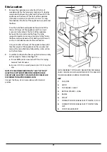
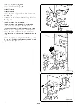
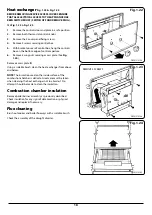
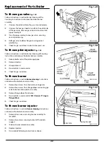
Preliminary installation
The appliance is delivered assembled with the exception of
the following items which are supplied separately packed
and require assembly.
1.
Draught Diverter Assembly
See
Fig. 1.4
.
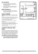
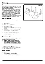
2.
Appliance Rear Distance Bracket:
(for use when
appliance is installed (25mm) away from a rear wall of
combustible material). See
Fig. 1.5
.
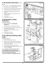
3.
Hand Rail:
The handrail brackets are held on the front
ends of the cooker top-plate casting. Remove the travel
nuts and replace with the handrail brackets ensuring
the fibre protecting washers are in position. Insert
the handrail with fitted endcaps in to the brackets,
positioning them correctly, and tighten the locating
bolts (
Fig. 1.6
).
Installation Instructions
Fig. 1.4
Fig. 1.5
Fig. 1.6
DESN 512141 A
DESN 512142
DESN 510454 ‘A’
25mm
COMBUSTIBLE
WALL LINE
BRACKETS
SCREWED TO BACK
EDGE OF BOTH
SIDE PLATES WHEN
COMBUSTIBLE WALL
IS UTILISED ON
INSTALLATION


