11
P/N 42-9472 Copyright 2008 Mestek, Inc.
Cast iron condensing boiler
Cast iron condensing boiler
— Control manual
External interlocks
Wire external limits and fl ow switch, when used, as shown in Figure 8, page 10.
If wiring to and from a motorized combustion air damper, follow the guidelines
given in Figure 8, page 10. Connect only to the master boiler.
If any of the member boilers is to operate in override mode, and the
system is equipped with a combustion air damper, you must provide
special wiring in order to ensure the damper opens and proves when
the boiler fi res. Th is must be done without compromising the wiring
between the master boiler and the damper.
Overrides — Control priorities
Th e 200i control can provide override operation for any or all member boilers in a
SmartCycle network. Th is requires the boilers be piped with appropriate isolation
piping and controls.
Override is done by closing a contact across the Heat Demand or DHW Demand
terminals of any boiler. Th ese priority inputs override all network controls or 4-
20mA input controls to the boiler.
DHW Demand
— Th e DHW Demand closure takes priority for ALL boilers, in-
cluding the master and all members. When DHW Demand closes, the boiler or
boilers immediately switch to DHW operation, including sett ing the water tem-
perature to the DHW Setpoint.
Space heating, Heat Demand
— If any member boiler sees closure across its
Heat Demand terminals it will begin operation in space heating mode indepen-
dently of commands from the master boiler or 4-20mA input source.
Do not wire boilers for override operation unless the piping design
provides automatic isolation of the overriding boilers. Th e master
boiler would be unable to properly control system water temperature
if member boilers were to input heat to the system without control
from the master. DHW operation, in particular, would raise the supply
temperature from overriding boilers to the DHW Setpoint.
Override operation control setup — Boilers must be set up with
operating parameters necessary during their override operation; i.e.,
local setpoint, DHW setpoint, etc.
Summary — priority sequence is:
Priority 1 = DHW Demand
Priority 2 = Heat Demand
Priority 3 = SmartCycle input
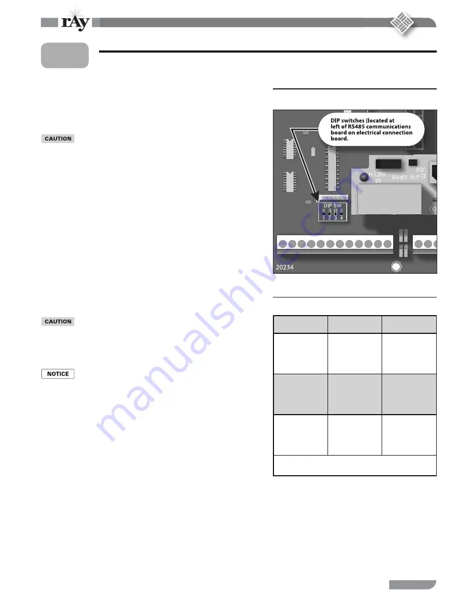
Set termination DIP switches
Th e SmartCycle network needs to recognize the beginning and end of the
network. Th is requires sett ing the four DIP switches on each boiler’s electrical
connection board.
See Figure 9 for location of the switches.
See Table 1 for required sett ings. Th e table gives sett ings for SmartCycle modula-
tion — local control and for remote control from a building management system
(Modbus protocol).
DO NOT connect the communications cables (or shielded wires) between boilers
until all boilers have had parameters set and then been started up following all in-
structions in the 200i Boiler manual.
1.
2.
3.
4.
5.
6.
7.
1.
2.
3.
4.
Figure 9
Termination DIP switches (see item 7, Figure 7,
page 9 for location)
Table 1
Termination DIP switch settings
Boiler
SmartCycle
Modbus
(see note)
Master
Switch 1: ON
Switch 2: ON
Switch 3: OFF
Switch 4: OFF
Switch 1: ON
Switch 2: ON
Switch 3: ON
Switch 4: ON
Last member
Switch 1: ON
Switch 2: ON
Switch 3: OFF
Switch 4: OFF
Switch 1: ON
Switch 2: ON
Switch 3: OFF
Switch 4: OFF
Other members
Switch 1: OFF
Switch 2: OFF
Switch 3: OFF
Switch 4: OFF
Switch 1: OFF
Switch 2: OFF
Switch 3: OFF
Switch 4: OFF
Note: Modbus setup is for applications controlled by a building management system. For
systems using BACnet or LonWorks, a bridge board is used to interface with the 200i
control. Th e switch is “on” when in the down position and “off ” when in the up position.
Method 1: SmartCycle modulation – local control
(cont.)
1


