Raven SC1 Скачать руководство пользователя страница 52

CHAPTER 5

48

Raven SC1™/TC1™ (software version 1.5) Calibration & Operation Manual for Tractors and Sprayers

3. Select the Accept button in the lower, right corner of the page to return to the Steering Setup tab.

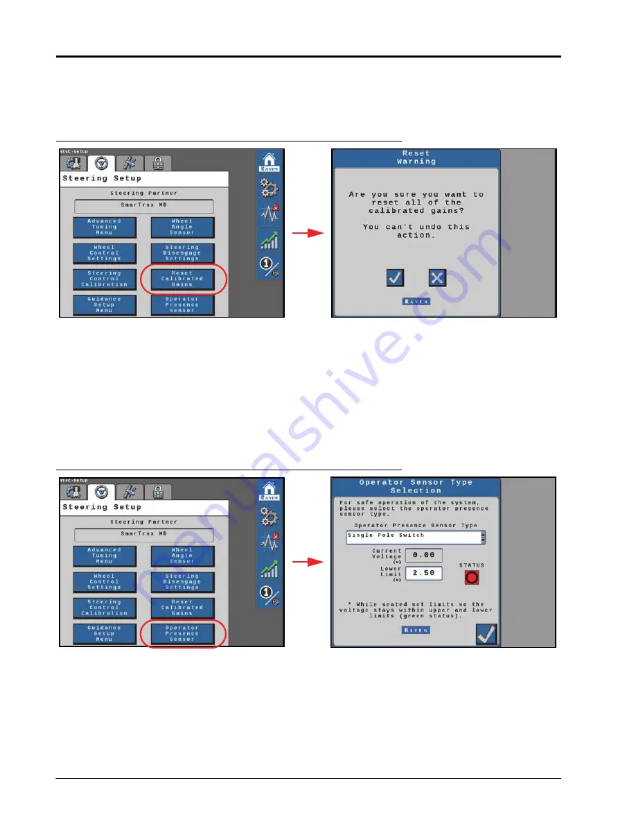
RESET CALIBRATED GAINS

FIGURE 19. Reset Calibrated Gains Page

To reset the SC1/TC1 system to factory defaults:
1. From the SC1/TC1 Home page, select the Settings Menu button.
2. Select the Steering Setup tab and the Reset Calibrated Gains button.
3. Review the warning prompt and select the Accept button to reset the SC1/TC1 to a factory condition. Select the 

Cancel button to keep the current system configuration and return to the Steering Setup tab.

OPERATOR PRESENCE SENSOR

FIGURE 20. Steering Disengage Settings Page

SENSOR TYPE

Use the drop down list to select the type of switch used to detect the presence of the operator while the system is 

engaged.
• Single  Pole
• Double  Pole
• CAN  Switch

Содержание SC1

Страница 1: ...Copyright 2019 2020 2022 Raven SC1 TC1 Calibration Operation Manual for Tractors and Sprayers 016 4010 005 Rev G 10 2022 E43551 ...

Страница 2: ...aven Industries shall not be held responsible for any modifications or repairs made outside our facilities nor damages resulting from inadequate maintenance of this system As with all wireless and satellite signals several factors may affect the availability and accuracy of wireless and satellite navigation and correction services e g GPS GNSS SBAS etc Therefore Raven Industries cannot guarantee t...

Страница 3: ...ion 8 GPS Setup 9 Terrain Compensation Calibration 14 Auto Steering Calibration 16 Chapter 4 Routine Machine Operation 25 Operator Liability 25 Home Page 26 Steering Status Indicator 26 Off Line Indicator 27 GPS Status Indicator 27 Tuning Settings 27 Steering Status Page 28 Status Displays 29 GPS Status Page 32 CRX Features and Operation 33 CRX Widget Definitions 33 Engaging SC1 TC1 34 Chapter 5 M...

Страница 4: ...t Configuration 54 GPS Receiver Setup 59 Differential Configuration Page 59 GPS Information 60 Chapter 7 Feature Unlock Codes 63 Chapter 8 Aux Input Setup and Operation 65 ID Function 1 10 Definitions 65 ID Function 11 Definitions 66 Chapter 9 Diagnostics and Troubleshooting 67 Diagnostic Trouble Codes DTC 67 Diagnostic Trouble Code DTC List 69 System Health Tests 84 Step Response Test 84 Machine ...

Страница 5: ...ce Be alert and aware of surroundings and remain in the operator seat at all times when operating this Raven system Do not operate the implement on any public road with this Raven system enabled Disable this Raven system before exiting the operator seat Determine and remain a safe working distance from obstacles and bystanders The operator is responsible for disabling the system when a safe workin...

Страница 6: ...recommended around the GNSS antenna to help avoid common issues with signal interference Do not mount cellular radio or other GNSS antennas within this area Mount the GNSS antenna to the tallest point of the machine Avoid mounting the antenna in a location where obstructions e g bins hoppers cab roof lines equipment frame or structural elements etc may rise into the antenna view NOTE The antenna v...

Страница 7: ...iculation and pivot points Clamp harnessing securely to force controlled movement of the harness Avoid abrasive surfaces and sharp edges such as sheared or flame cut corners fastener threads or cap screw heads hose clamp ends etc Do not connect affix or allow harnessing to come into contact with components with high vibration forces hot surfaces or components carrying hot fluids beyond the tempera...

Страница 8: ...CHAPTER 1 4 Raven SC1 TC1 Calibration Operation Manual for Tractors and Sprayers ...

Страница 9: ...eaders and tractors When coupled with an implement steering system SC1 TC1 is capable of keeping both your tractor and a towed implement on track The chapters in this manual are intended to assist with the proper calibration and operation of the SC1 TC1 system FIGURE 1 SC1 TC1 Home Page SYSTEM SPECIFICATIONS SC1 TC1 ELECTRICAL RATING The specifications below are specific to the SC1 TC1 system Curr...

Страница 10: ...he website WARNING Carefully read and follow all safety requirements and precautions contained in this manual and the machine specific or implement Installation Manual Failure to follow safety instructions may lead to equipment damage personal injury or death At Raven Industries we strive to make your experience with our products as rewarding as possible One way to improve this experience is to pr...

Страница 11: ... auto steering calibration the machine will make several hard left and right turns Adjust the vehicle speed and location as necessary NOTICE Calibration of the machine steering system should be performed in a field or other large open space and with conditions similar to normal vehicle operation If the ground or surface is slippery muddy or freshly tilled the SC1 TC1 system may learn incorrect ste...

Страница 12: ...he auto steering calibration the machine will make several hard left and right turns Adjust the vehicle speed and location as necessary To pause the calibration at any time turn the steering wheel or press the Stop button on the UT Tap the foot resume switch to resume the calibration process To ensure successful auto steering calibration try to minimize the number of pauses If an error message is ...

Страница 13: ... the Machine Type Machine Make and Machine Model most closely matching the equipment used for the current machine configuration 4 When all options have been set select the Next button One of the two following pages will be displayed Steering Partner Not Found Steering Configuration FIGURE 1 Steering Partner and Configuration 5 Select the GPS Only Configuration button to set up and use only the GPS...

Страница 14: ...election FIGURE 3 Antenna Fore Aft Page 7 Select the value box to enter the Antenna Fore Aft position NOTE The Antenna Fore Aft Offset is measured from the rear axle of the machine to the center of the GPS antenna A negative value should be entered if the GPS antenna is located behind the rear axle 8 Select the Next arrow ...

Страница 15: ...er Offset position is measured from the centerline of the machine to the center of the GPS antenna A negative value should be entered if the GPS antenna is located to the left of the centerline 10 Select the Next arrow FIGURE 5 Antenna Height Page 11 Select the value box to enter the Antenna Height NOTE The Antenna Height is measured from the ground to the mid point of the GPS antenna 12 Select th...

Страница 16: ...e machine Add these measurements together and then divide by 2 to get the average Wheel Base value 14 Select the Next arrow FIGURE 7 GPS Differential Configuration Page 15 Select the appropriate GPS Differential Configuration from the drop down box NOTE Some differential sources may require a feature unlock Refer to Chapter 7 Feature Unlock Codes for additional assistance with entering feature unl...

Страница 17: ...isplayed and select the Next button to proceed with the calibration process NOTE The GPS solution must be converged to calibrate and proceed with the initial system calibration 18 Select the Next arrow 19 Use the rotation buttons until the on screen display matches the orientation of the SC1 TC1 ECU FIGURE 9 SC1 TC1 ECU Orientation 20 Select the Next arrow ...

Страница 18: ... and park on a flat surface NOTE The SC1 TC1 system must detect the direction of forward travel to properly calibrate the terrain compensation features FIGURE 11 Terrain Compensation Calibration page 2 2 Stop the machine on a level surface 3 Place flags or markers to mark rear tire position on each side of the machine 4 Select the Next button and follow the on screen instructions to begin the terr...

Страница 19: ...the page Wait for the calibration process to be completed before moving the vehicle 7 Drive forward and turn the machine around 180 Park the vehicle between the markers facing in the opposite direction as when the Calibrate button was first selected Make sure the markers are aligned with the pivot point of the machine on opposite sides of the machine FIGURE 14 Step 2 Machine Orientation to Complet...

Страница 20: ... Wizard Summary will be displayed Touch the Accept button to go to the GPS Only Home page Refer to Chapter 4 Routine Machine Operation for assistance with operating the SC1 TC1 system in GPS only mode If calibrating the auto steering features continue to the next section to continue the SC1 TC1 system calibration FIGURE 16 Calibration Summary AUTO STEERING CALIBRATION The Auto Steering calibration...

Страница 21: ...n Screen Engage option to use an on screen engage widget to start and stop auto steering during SC1 TC1 operation FIGURE 18 Disengage Switch Calibration Page 2 Turn the steering wheel to calibrate the disengage sensor The status icon will change if the input is detected and the calibration with automatically proceed to the next page NOTE In a SmarTrax MD HD system a page displaying the calibrated ...

Страница 22: ...ck 3 Select the Left button to set the left WAS value NOTE Do not move the steering wheel until the calibration page advances to the Center WAS setting FIGURE 20 Center WAS Calibration Page 4 While driving forward between 2 6 km h 1 4 mph recenter the steering wheel to drive straight ahead 5 Select the Center button to set the center WAS value NOTE Do not move the steering wheel until the calibrat...

Страница 23: ...AS Calibration Complete Page 9 Review the WAS calibration details 10 Press the Next arrow HYDRAULIC SYSTEM CALIBRATION The steering control calibration process allows the SC1 TC1 system to learn the hydraulic capabilities of the machine for optimal steering performance in the field NOTE Review the Preparation and Best Practices section on page 8 for tips on completing the auto steering calibration...

Страница 24: ... 1 Accept the Roadway Homologation terms Carefully review the on screen disclaimer and select the check box option FIGURE 23 Roadway Homologation NOTE Refer to the Chapter 11 Roadway Homologation for additional information about the SC1 TC1 homologation terms and certifications 2 Select the Next arrow NOTICE Calibration of the machine steering system should be performed in a field or other large o...

Страница 25: ...process is complete select the Accept button WARNING The machine will steer automatically While calibrating or operating the SC1 TC1 system be sure the area around the vehicle is clear of people and obstacles before engaging the steering system To disengage auto steering at any time turn the steering wheel or select the on screen Stop button WARNING Always remain in control of the machine During t...

Страница 26: ...uto Calibration Complete CALIBRATION SUMMARY 1 Review the Calibration Wizard Summary information FIGURE 26 Calibration Wizard Summary 2 Select the Accept button to complete the calibration process Refer to Chapter 4 Routine Machine Operation for assistance with operation of the SC1 TC1 guidance and steering system ...

Страница 27: ...Initial Machine Calibration Initial Machine Calibration 23 INITIAL MACHINE CALIBRATION FIGURE 27 SC1 TC1 Home Page ...

Страница 28: ...CHAPTER 3 24 Raven SC1 TC1 software version 1 5 Calibration Operation Manual for Tractors and Sprayers ...

Страница 29: ...on manual for assistance with setting up and starting a job setting guidance lines and other guidance settings during in field operations OPERATOR LIABILITY The Operator Liability Warning is displayed each time the SC1 TC1 system is powered on If the operator does not accept liability the SC1 TC1 system will be disabled and cannot be reengaged until the liability warning is accepted FIGURE 1 Opera...

Страница 30: ... while the SC1 TC1 system is on the ISOBUS Select the steering wheel icon to display the Steering Status page Refer to the Steering Status Page section on page 28 for additional assistance with the information available on this page Display Message System critical DTCs are present The SC1 TC1 system cannot be engaged in this state Refer to Chapter 9 Diagnostics and Troubleshooting for assistance w...

Страница 31: ... line with the hitch pin in the same location If the hitch pin does not line up with the flag divide the number of inches cm by two and enter that value into the Antenna Shift field If the hitch pin falls to the right of the flag enter a positive Antenna Shift value If the hitch pin falls to the left of the flag enter a negative value Sensitivity The Sensitivity value determines how aggressively t...

Страница 32: ...sponse Speed value in increments of 10 If steering does not become jittery the Response Speed value may be increased in increments of 10 until the desired Response Speed is reached Last Pass Sensitivity non Tractors Only The Last Pass Sensitivity determines how tightly the machine tries to steer on a curved path Too high of a value will cause the machine to steer to the inside of a curve Too low o...

Страница 33: ...eering Status History page to display a description of the disengagement code FIGURE 5 Info Button Information STATUS DISPLAYS MASTER SWITCH Display Message The master switch is set to road mode The SC1 TC1 system cannot be enabled until the master switch is toggled to field mode The master switch is set to field mode and the SC1 TC1 system can be enabled ...

Страница 34: ...e status of the position sensor Display Message The resume switch is set in the OFF position The resume switch is in the ON position Display Message The SC1 TC1 disengage sensor is active The SC1 TC1 system cannot be enabled The SC1 TC1 disengage sensor is out of range or disconnected The SC1 TC1 disengage sensor is inactive The SC1 TC1 system can be enabled Display Message The wheel angle sensor ...

Страница 35: ...cted by the ECU NOTE Front wheel steering will be displayed for all machines not equipped with a second steerable axle or for machines not compatible with this feature Display Message The presence switch is not available or not used with the selected machine profile The operator is not present in the seat The operator presence switch is disconnected The operator presence switch detects the operato...

Страница 36: ...ceiver Number of Satellites The number of satellites currently in view by the GPS receiver HDOP Horizontal Dilution of Precision A higher value indicates that the satellites currently used for the machine position are grouped closer together and accuracy may be reduced If the satellites are too close the system may record a High HDOP DTC Age of Differential Time in seconds since the last different...

Страница 37: ...or additional status conditions which may be displayed in the SC1 TC1 on screen widget Display Message The SC1 TC1 node is detected but the operator must accept responsibility for the operation of the SC1 TC1 system No A B path or guidance line has been set or an active DTC is preventing the SC1 TC1 system from engaging SC1 TC1 is detected turned on and calibrated A non critical DTC is present SC1...

Страница 38: ...on and Operation manual P N 016 0171 539 for further information on adding widgets NOTE The operator liability waiver must be accepted before the SC1 TC1 system can be enabled for operation The SC1 TC1 steering may also be engaged using the following methods Tap the foot switch or rocker switch to engage SC1 TC1 features during field operation Press the SC1 TC1 on screen status widget to engage th...

Страница 39: ...guration Page To view the current machine configuration 1 From the SC1 TC1 Home page select the Settings Menu button 2 On the Machine Settings tab select the Machine Configuration Information button 3 The current machine type make and model information that was entered during the calibration process The Machine Configuration settings cannot be changed unless the SC1 TC1 system is recalibrated ...

Страница 40: ...ation about the settings shown on the page Antenna Height The Antenna Height is measured from the ground to the middle of the GPS antenna Antenna Center Offset The Antenna Center Offset position measured from the centerline of the machine to the center of the GPS antenna A negative value should be entered if the GPS antenna is located to the left of the center line Antenna Fore Aft The Antenna For...

Страница 41: ...ct a different profile create a new profile or recalibrate the current profile 1 From the SC1 TC1 Home page select the Settings Menu button NOTE The name of the current profile selected is displayed at the top of the Machine Settings tab 2 Select the Change Profile button NOTE Up to 5 machine profiles may be saved for the SC1 TC1 system 3 Use the radio buttons to select a different profile Selecti...

Страница 42: ...IGURE 6 Node Orientation To adjust the node orientation 1 From the SC1 TC1 Home page select the Settings Menu button 2 On the Machine Settings tab select the Node Orientation button 3 The Node Orientation page displays the currently configured orientation of the SC1 TC1 ECU To change the orientation restart the profile set up NOTE The SC1 TC1 ECU must be mounted in a horizontal orientation Vertica...

Страница 43: ...e to an off track error while a lower value indicates a less aggressive response Heading Gain Determines how aggressively the SC1 TC1 system responds to a heading error A higher Heading Gain value results in a more aggressive response to a heading error while a lower value indicates a less aggressive response Yaw Rate Gain Determines the impact of the yaw rate on tracking performance A higher Yaw ...

Страница 44: ...ge Proportional Gain Determines the rate of the wheel response Increasing the Proportional Gain value causes the wheel response to be faster but can result in the machine overshooting the target wheel angle position or can cause the wheels to take a longer time to stabilize Integral Gain This value corrects long term errors in the steering control loop This setting should be adjusted by qualified ...

Страница 45: ...this option if the hydraulic hoses are connected in reverse orientation e g when steering left moves the wheels right etc Wheel Velocity The speed at which the wheels are moving measured in degrees per second Control Effort The amount of effort the SC1 TC1 system is using to drive the wheels Valve Motor Current Displays the current draw of the steering valve steering motor Left Right MIN MAX Touch...

Страница 46: ... TC1 to the machine hydraulic system without completing the full SC1 TC1 system calibration NOTE Review the Preparation and Best Practices section on page 8 for tips on preparing for and completing the calibration process WARNING The machine will steer automatically While calibrating or operating the SC1 TC1 system be sure the area around the vehicle is clear of people and obstacles before engagin...

Страница 47: ...eel Control Calibration button 3 Drive the machine forward at 1 4 mph 2 6 km h 4 Press the resume switch or use the on screen Start button to begin calibration SC1 TC1 will display the progress of the calibration 5 When the calibration is complete select the Accept button in the lower right corner of the page to return to the Steering Setup tab GUIDANCE SETUP MENU If a Raven VSN visual guidance sy...

Страница 48: ...r line acquire via GPS with the system switching to the VSN camera when the machine is aligned and near the guidance line This mode will also fall back to GPS guidance if the solution quality falls below the minimum threshold The system will then return to VSN guidance automatically when the solution quality is above the minimum threshold AUTOMATION LEVEL Set the mode for devices installed on an O...

Страница 49: ...s and Tuning Steering Setup Tab 45 MACHINE SETTINGS AND TUNING FIGURE 16 Guidance Path Partner Page Guidance Path Partner Displays the recognized device which provides a guidance path for the automated steering system ...

Страница 50: ...ete the following steps to adjust or tune the wheel angle sensor WAS Current Sensor Voltage Displays the sensor voltage detected during calibration Current Wheel Angle Displays the WAS angle detected during calibration Center Learning When selected the Center Learning option the system will continuously correct its calibrated center position while the machine is steering straight ahead 3 Drive the...

Страница 51: ...to activate the disengage switch If the disengage switch is not activated check cabling for loose or missing connections Disengage Threshold Set the threshold for when the steering disengage switch disengages auto steering Adjust the value so that the disengage status changes to red when the steering disengage switch is engaged When the steering input stops this status should return to green which...

Страница 52: ...select the Settings Menu button 2 Select the Steering Setup tab and the Reset Calibrated Gains button 3 Review the warning prompt and select the Accept button to reset the SC1 TC1 to a factory condition Select the Cancel button to keep the current system configuration and return to the Steering Setup tab OPERATOR PRESENCE SENSOR FIGURE 20 Steering Disengage Settings Page SENSOR TYPE Use the drop d...

Страница 53: ...mit This is the voltage at which the switch will toggle when the operator is seated or the Activity Monitor is enabled UPPER LIMIT DOUBLE POLE SWITCH ONLY Use this setting to adjust the upper voltage limit Set the upper limit so that the current voltage reading remains below the upper limit while the operator is seated If the presence switch voltage exceeds the upper limit the presence switch will...

Страница 54: ...CHAPTER 5 50 Raven SC1 TC1 software version 1 5 Calibration Operation Manual for Tractors and Sprayers ...

Страница 55: ...IPER 4 FIGURE 1 ROS Settings DGPS Settings 1 Select Edit 2 Select GPS FIGURE 2 GPS Setup Page 3 Select NMEA2000 NOTE The ROS device will automatically select NMEA 2000 If there are multiple devices outputting NMEA messages be sure that the correct device to allow the RS1 to ensure proper operation of the SC1 system ...

Страница 56: ...eceivers to output the correct messages and message rates Raven 600S Raven 700S Viper 4 4 Viper 4 4 Twin If a different receiver is being used configure the receiver output to the settings below before performing calibration TABLE 1 GPS Receiver Message Settings NOTE Refer to Chapter 10 Trimble 372 Configuration using AgRemote for assistance with these settings when using a Trimble receiver Baud R...

Страница 57: ...ude No Signal Error Converging Converged Current Accuracy A value representing the reported horizontal accuracy of the current solution as detected by the receiver Accuracy Threshold Set the maximum distance allowed for the Current Accuracy value If the Current Accuracy value is greater than the set Accuracy Threshold a DTC entry will be recorded on the Diagnostic Trouble Code page Select the Acce...

Страница 58: ...UT CONFIGURATION FIGURE 6 GPS Serial Output Serial Output Configuration Page GPS Output Allows the SC1 TC1 system to output NMEA 0183 messages at configurable rates See the GPS Serial Output Configuration section on page 57 for details Radar Out Use the radar out option to output a simulated radar speed Radio Modem Select Radio Modem to configure the radio modem See the Radio Modem Configuration s...

Страница 59: ...em type will display here Modem type options are 450 MHz 900 MHz Radio Base Allows the user to toggle between stored radio bases 4 Select New in the Radio Base drop down list to setup a new radio base station NOTE If a base station has already been configured use the Base Name drop down field to select the stored base station for SC1 TC1 operation Select the Accept button in the lower right corner...

Страница 60: ...n configuring a 450 MHz radio modem enter the radio frequency and select the proper Mode from the drop down FIGURE 9 450 MHz Modem Modes Page 7 Select the Accept button in the lower right corner of the page to save the displayed radio modem settings and return to the Serial Output Configuration page 8 Select the Accept button again to return to the Machine Settings tab ...

Страница 61: ...rn to the Serial Output Configuration page FIGURE 10 Configured Radio Base Pages 7 Select the Accept button in the lower right corner of the page to return to the GPS Setup tab GPS SERIAL OUTPUT CONFIGURATION To configure GPS message output from or passed through the SC1 TC1 system 1 From the SC1 TC1 Home page select the Settings Menu button 2 Select the GPS Setup tab and the Serial Output Configu...

Страница 62: ...tem 1 From the SC1 TC1 Home page select the Settings Menu button 2 Select the GPS Setup tab and the Serial Output Configuration button 3 Select RTK Out from the Config Types drop down to output 3D compensated RTK to another ECU 4 Select the Baud rate for corrections 5 Select the Accept button in the lower right corner of the page to return to the GPS Setup tab FIGURE 12 RTK Out Settings Page ...

Страница 63: ...figured to output the correct messages if the Receive Only option is selected Refer to the Configure GPS in the Viper 4 Viper 4 section on page 51 for additional information on required GPS receiver outputs for SC1 TC1 FIGURE 13 GPS Setup Page 4 Select the Accept button in the lower right corner of the page to return to the GPS Setup tab DIFFERENTIAL CONFIGURATION PAGE To set the differential solu...

Страница 64: ...e GPS Setup tab and the GPS Information button The following information will be displayed FIGURE 15 GPS Information Page Latitude The angular distance of a place north or south of the earth s equator Longitude The angular distance of a place east or west of the meridian at Greenwich England Elevation MSL The height of the antenna in reference to sea level Speed Current speed based on GPS measurem...

Страница 65: ...es in view are from the same direction the number will be higher and the accuracy will be reduced Heading The current direction of travel Differential ID The ID of the satellite used for differential corrections Age of Differential Time in seconds since the last differential correction was received When using the GL1DE corrections or if a differential source is not currently tracked this entry wil...

Страница 66: ...CHAPTER 6 62 Raven SC1 TC1 Calibration Operation Manual for Towed Implements ...

Страница 67: ...TE Contact your local Raven dealer for additional information and assistance with purchasing activation and feature unlock codes FIGURE 1 Feature Unlock Page To activate features of the SC1 TC1 steering system 1 From the SC1 TC1 Home page select the Settings Menu button 2 Select the Feature Unlocks tab 3 Select the Lock icon next to the feature to be activated FIGURE 2 Feature Unlock Information P...

Страница 68: ...ct the Accept button NOTE SC1 TC1 will display a message indicating whether the unlock code is valid If the code is accepted the padlock will turn green and indicate that the feature is ready for use FIGURE 3 Feature Unlocks Page NOTE GS Lite Satellite GS and RTK unlocks can only be applied for the following GPS Receivers Raven 600S Raven 700S Viper 4 4 Twin Viper 4 4 ...

Страница 69: ... for additional assistance with device configuration features and options FIGURE 1 Grayhill Remote Page 4 Use the Input ID drop down options to select a function or button on the Grayhill remote 5 Next use the ID Function list to assign a desired action to the button NOTE Input ID number 11 on the Grayhill remote is a rotary button ID FUNCTION 1 10 DEFINITIONS The following functions can be used f...

Страница 70: ...center the implement guidance line Nudge Camera Offset Left This function is used to nudge the implement camera offset to the left 0 5 cm 0 2 in Nudge Camera Offset Right This function is used to nudge the implement camera offset to the right 0 5 cm 0 2 in ID FUNCTION 11 DEFINITIONS The following functions can be used for ID 11 Nudge Guidance Line This function is used to nudge the guidance line l...

Страница 71: ...TC1 system operation Active DTCs must be fixed before the SC1 TC1 system can be enabled for guidance and steering operation Once a DTC has been corrected the code moves to the inactive DTC code list Refer to Figure 3 for an example of DTCs and DTC summaries FIGURE 2 Diagnostic Trouble Codes Page NOTE In Figure 3 above the active DTC is 522250 31 and the DTC summary is No Guidance Points The inacti...

Страница 72: ...ual for Towed Implements FIGURE 3 Info Prompt Pressing the Info button displays the complete description of the highlighted active DTC FIGURE 4 Inactive DTCs Cleared from Error Log Pressing Clear deletes the inactive DTCs from the Inactive DTC error log ...

Страница 73: ... not exceed the maximum auto steering speed refer to 74 0 above SC1 TC1 maximum steering warning DTC is triggered at 16 1 km h 10 mph for machines operating in Europe with homologation terms accepted 29 km h 18 mph for tracked machines and swathers 43 5 km h 27 mph for units capable of high speed steering and not subject to homologation terms Contact a local Raven dealer for additional assistance ...

Страница 74: ... Cycle power to the machine 11 GPS error 1 Ensure the SC1 TC1 ECU is calibrated and the desired differential source is unlocked 2 Wait for GNSS to converge up to 10 minutes 3 Ensure that NMEA 2000 is selected Review the GPS Setup section on page 9 15 Poor GPS position accuracy 1 If using Satellite GS or RTK corrections ensure that the GNSS quality is as expected for those correction sources Review...

Страница 75: ... the sensor voltage 5 V and current 4 20 mA Review the Resume Disengage Settings section on page 47 for assistance with the disengage switch settings 5243 2 Master switch is in the off position 1 Toggle the master switch ON or to field mode 2 Toggle the hydraulic lock switch to the unlocked state 3 Check CAN communication to the steering valve 5613 11 Field terrain compensation not calibrated Perf...

Страница 76: ...erformance Refer to the Wheel Control Settings section on page 41 for additional assistance 8 Lookahead too large Contact Raven technical service 522260 31 No guidance partner Field computer is not registered as a guidance partner 1 Cycle power to the Raven field computer 2 Update the field computer software 522261 31 No steering control unit SCU detected 1 Check cabling and connections to the ste...

Страница 77: ...securely to a flat surface Confirm that any sunroofs are closed If the issue persists re calibrate the terrain compensation Review the Terrain Compensation Setup section on page 54 for additional assistance 523766 31 Steering control partner serial number mismatch Select the correct steering profile or connect to the correct machine and steering control unit 523827 0 Reverse steer not supported Re...

Страница 78: ...el 523859 31 GPS receiver error external oscillator locked 523860 31 GPS receiver error software resource 523861 31 GPS receiver error Auxiliary 3 event 523862 31 GPS receiver error Auxiliary 2 event 523863 31 GPS receiver error Auxiliary 1 event 523864 31 GPS source mismatch Machine and implement steering systems are using different correction type Ensure that the machine and the implement are se...

Страница 79: ...r tracking mode 523922 31 GPS receiver error digital filter enabled 523923 0 VSN data invalid warning VSN is unable to provide valid row guidance Check the camera feed and solution quality from the VSN object pool Home page 523924 0 VSN data invalid error VSN guidance vectors not valid Restart the VSN 523925 2 No row camera communication VSN times out after 10 seconds Check cabling and connections...

Страница 80: ...ge 4 HC hight current low voltage Input voltage is below the lower limit 9 V 1 Check cabling for broken or frayed wiring 2 Check the machine battery voltage 628 2 NVM non volatile memory warning 1 Cycle power to the machine 2 Contact Raven technical support if the error persists 31 NVM non volatile memory Error 630 13 SCU steering controller unit not calibrated Complete the profile calibration wiz...

Страница 81: ... 86 for assistance with testing the operator presence sensor 31 Operator presence warning The operator override sensor is OFF The steering system is about to disengage Refer to the Machine Test section on page 86 for assistance with testing the operator presence sensor 2901 2 Incompatible hardware Update the SC1 TC1 software version Refer to the Raven field computer operation manual for additional...

Страница 82: ...sensor signal voltage is below the expected range 1 Recalibrate the WAS Review Wheel Angle Sensor Settings section on page 46 for additional assistance 2 Check mounting of the WAS or for damage to the WAS 3 If the problem persists contact a local Raven dealer for additional assistance 5 SID 1 signal high The disengage sensor signal 1 is above the upper limit 1 Cycle power to the machine 2 Ensure c...

Страница 83: ... Settings section on page 47 for assistance 3 Check the switch cabling and the sensor voltage current 4 If the problem persists contact a local Raven dealer for further assistance 253875 13 SCU software compatibility The steering control unit HDU MDU or IDU software is incompatible with the steering guidance control unit Update the MDU HDU software to a supported version 523877 13 SPI serial perip...

Страница 84: ...o the left or right PWM valve does not match return 1 Ensure cable connections are properly seated 2 Contact a local Raven dealer for additional assistance 5 PWM pwr current mA low Amperage supplied to the left and right solenoids is too low 1 Ensure cable connections are properly seated 2 Check for broken or frayed wiring 6 PWM pwr current mA high Amperage supplied to the left and right solenoids...

Страница 85: ... DB in Amperage supplied to double blocker solenoid does not match amperage return 1 Ensure cable connections are properly seated 2 Check for supply voltage on the connections to the machine steering valve 3 Contact a local Raven dealer for additional assistance 5 DB pwr power current mA low Amerage supplied to double blocker solenoid too low 1 Ensure cable connections are properly seated 2 Check ...

Страница 86: ...nsor e g wheel angle sensor disengage sensor etc is too high 1 Ensure cable connections are properly seated 2 Check for shorts in the wiring 523897 0 Safety micro comm err No communication to the safety micro 1 Cycle power to the machine 2 Contact a local Raven dealer for additional assistance if the problem persists 523899 3 WAS 1 signal high 1 Check the wheel angle sensor and sensor mounting for...

Страница 87: ...steering valve offers LED status lights review the machine operator manual for additional troubleshooting procedures 523908 31 No SGC steering guidance controller detected The steering guidance controller SC1 TC1 has not detected a navigation controller on the CAN bus 1 Ensure cable connections are properly seated 2 Inspect connectors for damage including missing bent or unseated pins 3 Check CAN ...

Страница 88: ...rformed via the SC1 TC1 system Step Response Test Machine Test STEP RESPONSE TEST The Step Response Test is used to determine the responsiveness of the implement steering system FIGURE 6 Step Response Test Page 1 Drive forward 1 4 mph with the engine RPM set at 3 4 throttle WARNING The machine will steer automatically while system heath tests are being performed Be sure the area around the vehicle...

Страница 89: ...ph with the engine RPM set at 3 4 throttle 6 Press the center up arrow Wait for the actuator to reach the center position 7 Press the right arrow 8 Wait for the following fields to populate and record the data a Step Size b Delay Time c Rise Time d Settling Time e Overshoot 9 To test consistency repeat steps 1 8 NOTE Once the Step Response Test has been completed the machine performance reading sh...

Страница 90: ...eering system FIGURE 8 Machine Test Page Use the drop down list options to select the following machine test pages Disengage Machine Info Readouts Switches MACHINE CONTROL EFFORT STEERING TEST The top of the Machine Test page allows the operator to test the steering system and valve control effort 1 Enter the test control effort percent in the left or right field ...

Страница 91: ...buttons to manually steer the wheels left or right 3 Select the X in the lower left corner to return to the Tests tab DISENGAGE Review the disengage switch settings and confirm switch operation and status FIGURE 10 Disengage Switch Test Page NOTE Adjust the Disengage Threshold value to test the disengage status based upon steering wheel inputs ...

Страница 92: ...une set profile information FIGURE 11 Machine Information Machine Test Page READOUTS Page offers information such as velocity wheel speed control effort for the steering valve the amperage per valve current pressure at each transducer if applicable and the WAS voltage FIGURE 12 Machine Test Readouts Page ...

Страница 93: ...chine steering master switch resume switch and operator presence switch The icons shown on this page should change when the switch status changes FIGURE 13 Machine Test Switches Page SYSTEM INFORMATION FIGURE 14 System Information Page 1 Select the desired device from the drop down menu 2 Select the desired system component from the second drop down menu ...

Страница 94: ...libration Operation Manual for Towed Implements FIGURE 15 System Information Pages SC1 TC1 Information Hardware Software Information SC1 TC1 Unit Hours Powered On SC1 TC1 Hardware Diagnostics GPS Receiver SC1 TC1 Unit Hours Engaged ...

Страница 95: ... and calibrated steering settings for the SC1 TC1 system FIGURE 17 Gains Summary Page The Gains Summary page displays all of the advanced steering settings used to steer the machine FIGURE 18 Preset Steering Gains The Preset Gains option allows the operator to switch back and forth between two sets of steering gain settings Different sets of settings may be useful when ...

Страница 96: ...ferent terrain conditions Different soil types Different speeds planting vs spraying FIGURE 19 Preset Gains Settings Press the button to toggle between the two sets of steering gains PERFORMANCE MONITOR FIGURE 20 SC1 TC1 Home Page 1 Select the Performance icon on the right side of the Machine Settings page to view the short term system performance ...

Страница 97: ...CS AND TROUBLESHOOTING FIGURE 21 Performance Monitor Pages NOTE The Short Term Performance page displays the averages and 95 performance values 2 Select the tab with the watch icon to view the Resettable Performance values 3 Select the Reset icon to reset the values ...

Страница 98: ...CHAPTER 9 94 Raven SC1 TC1 Calibration Operation Manual for Towed Implements ...

Страница 99: ...S CONFIGURATION 1 Press the Right button until Configuration displays on the screen 2 Press the Down button to select Configuration 3 Press the Right button until GPS Config displays 4 Press the Down button until Position Rate displays 5 Press Right to set the Position Rate to 10Hz FIGURE 2 Position Rate Setting 6 Press Enter to save the settings Escape Enter Up Down Right Left ...

Страница 100: ...ble CMRRadio FIGURE 3 Delivery Setting 7 Select Enter to save the settings PORT A CONFIGURATION 1 Press the Right button until Configuration displays on the screen 2 Press the Down button to select Configuration 3 Press the Right button until Port A Config displays 4 Press the Down button to select Port A Config 5 Ensure the Input I messages are set to None and the baud rate is set to 115K 6 Verif...

Страница 101: ...apitalized so they are turned on FIGURE 6 NEMA 2 Configuration 13 Press the Down button to continue configuring Port A 14 Press the Down button until CFG Port A Out RTS_CTS displays 15 Verify CFG Port A Out RTS_CTS is off FIGURE 7 Port A RTS CTS Configuration 16 Press Enter to save the settings 17 Press the Down button to continue configuring Port A 18 Press Enter to save the settings 19 Press the...

Страница 102: ...the setting is Report True Mode FIGURE 9 Port A NEMA Quality 24 Press Enter to save the settings PORT B CONFIGURATION 1 Press the Right button until Configuration displays 2 Press the Down button to select Configuration 3 Press the Right button until Port B Config displays 4 Press the Down button to select Port B Config 5 Verify the Input I messages are set to TSIP and the baud rate is set to 115K...

Страница 103: ...Trimble 372 Configuration using AgRemote 99 TRIMBLE 372 CONFIGURATION USING AGREMOTE FIGURE 10 Port B Configuration 7 Press Enter to save the settings ...

Страница 104: ...CHAPTER 10 100 Raven SC1 TC1 software version 1 5 Calibration Operation Manual for Tractors and Sprayers ...

Страница 105: ...e set Operating on the European continent Carefully review the on screen disclaimer before proceeding FIGURE 1 Roadway Homologation When roadway homologation is accepted the following parameters will be applied to SC1 TC1 operation An operator presence method will be required while operating with the SC1 TC1 auto steering system enabled Auto steering cannot be enabled above 10 mph 16 1 km h Auto s...

Страница 106: ...ned under no 1 and 2 is i n c o m p l i a n c e with the test specification mentioned above Das unter Nr 1 und 2 beschriebene System e n t s p r i c h t der o a Prüfspezifikation With regard to the required level of performance to be achieved the tested items were representative for the type to be validated Die verwendeten Prüfmuster waren im Hinblick auf das erforderliche Leistungs niveau für den...

Страница 107: ...tem Health Tests 84 Min PWM Sweep Test 89 Step Response Test 84 System Information 89 F Feature Unlock Codes 63 I Initial Machine Calibration 7 Introduction 5 Installation 6 Recommendations 6 Updates 6 M Machine Settings 35 R Routine Operation CRX Widget Definitions 33 Machine 25 S Steering Setup Advanced Tuning 39 Resetting Calibrated Gains 48 Resume Disengage Settings 47 Wheel Angle Sensor Setti...

Страница 108: ...Index 104 Raven SC1 TC1 software version 1 5 Calibration Operation Manual for Tractors and Sprayers ...

Страница 109: ...s product or any component of the product found to be defective during the warranty period Replacement will be made with a new or remanufactured product or component Standard return freight will be paid regardless of inbound shipping method Expedited freight is available at the customer s expense WHAT IS NOT COVERED BY THIS WARRANTY Raven Industries will not assume any expense or liability for rep...

Страница 110: ...by Raven Industries Applied Technology division This Extended Warranty coverage applies only to the original owner and is non transferable HOW CAN I GET SERVICE Bring the defective part and proof of purchase to your Raven dealer If the dealer approves the warranty claim the dealer will process the claim and send it to Raven Industries for final approval The freight cost to Raven Industries will be...

Страница 111: ...es Damages caused by normal wear and tear misuse abuse neglect accident improper installation and maintenance are not covered by this warranty Worn Chafed hoses and cables Items in contact with fluids and chemicals including seals and O rings Software downloads and updates Tamper Evident label broken or customer disassembly Any customer modification to the original product outside normal calibrati...

Отзывы: