background image


Header & Data Digests 


Digests  are  an  advanced  form  of  error-detection  specified  by  iSCSI.  These  may  be  used  for 
error detection on the iSCSI Headers and or the Data portion of the packet. Depending on the 
hardware  used, enabling  Digests  may  affect  the  performance  so  it  is  recommended  that  this 
option be only enabled when you suspect you are receiving corrupted IP packets.  

There are three encoding options for each of the Digests.  

• 

Selecting None forces Data Digests to off  

• 

Selecting CRC32 forces on Data Digests to use the CRC32 encoding.  

• 

Selecting the None/CRC32 option allows the initiator to select the whether 

Data Digests are enabled  

Current Connections 


This  section  lists  the  current  connections  i.e.  logged  on,  from  iSCSI  hosts.  It  displays  which 
initiator is connected to which Target device.  

Note it is possible that more than one host to be connected to any target device or one host to 
multiple target devices.  

It  is  possible  to  send  a  logout  request  to  a  host  by  highlighting  the  host  connection  and 
pressing the logout button  

Note:  many  initiators  are  configured  to  automatically  reconnect  after  completing  the  logout 
request. If this is the case then the connections window may not show any change.  

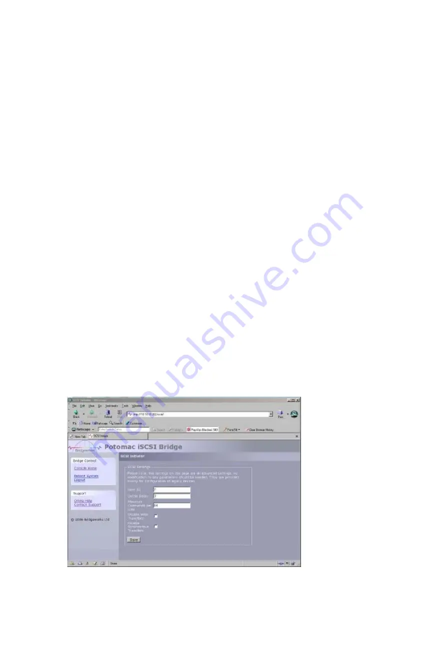
3.11 SCSI Bus 


This configuration  page  will allow the administrator to configure  a number of parameters that 
control the behaviour of the SCSI bus.  

From within the main menu select the SCSI Initiator icon from the SCSI System section.  

The GUI will now display the following window  


Page 13  

Содержание RT-iSCSI-R

Страница 1: ...INC 9155 Archibald Ave Suite 904 Rancho Cucamonga CA 91730 Tel 909 987 3966 Fax 909 989 2365 Web http www rancho com Email Support rancho com RT iSCSI R Small Enterprise Rack Mount iSCSI to SCSI Brid...

Страница 2: ...e This should be marked as certified to Cat 5e and have a RJ45 style connector at the Bridge end SCSI Cable The greatest source of SCSI related faults are due to poor quality SCSI cabling This is espe...

Страница 3: ...ress 3 4 Setting the IP Mask 3 5 Setting the Broadcast Address 3 6 Committing the Changes 3 7 Reconnect to the Bridge 3 8 Setting the Password 3 9 Network Services 3 10 iSCSI Connections 3 11 SCSI Bus...

Страница 4: ...section guide you through the initial set up required to install the Bridge on to your network 1 1 Overview The iSCSI Bridge creates an interface between a network which utilizes the Ethernet protoco...

Страница 5: ...BaseT 1000BaseT Gigabit It is not necessary to specify which network type you are connected to as the iSCSI Bridge when powered up it will automatically select the correct network speed The connection...

Страница 6: ...7 is reserved for the iSCSI Bridge The iSCSI Bridge can support both Single Ended and LVD peripherals However it should be noted that the two buses will have different data transfer speeds and cable l...

Страница 7: ...pply to the unit ensure the wall plug is removed or switched off Connect the Power Supply to the rear of the ISCSI Bridge as shown below Before powering up the iSCSI Bridge ensure all the peripherals...

Страница 8: ...ous sections and power up the unit From within your web browser connect to the ISCSI Bridge using the IP address 10 10 10 10 Depending on how the network parameters are set on the machine you are usin...

Страница 9: ...button under the Network section of the main window This will now bring up a new configuration page 3 2 Setting the Hostname In this box enter the name you wish to use to address this iSCSI Bridge in...

Страница 10: ...will be issued from the DHCP server If you are using static IP address enter the IP mask in this box 3 5 Setting the Broadcast Address Enter in this box your Broadcast address for your network 3 6 Com...

Страница 11: ...thout logging into the GUI so ensure you remember your password 3 9 Network Services This configuration page will allow the administrator to configure the IP addresses for the Network Time Domain serv...

Страница 12: ...word and username for the CHAP authorisation and the Data Digest error checking on the Bridge From within the main menu select the iSCSI Target icon from the SCSI System section The GUI will now displ...

Страница 13: ...onnections This section lists the current connections i e logged on from iSCSI hosts It displays which initiator is connected to which Target device Note it is possible that more than one host to be c...

Страница 14: ...time is the length of time given to allow devices to reset before issuing commands Some older devices may take longer than the default 3 seconds which may cause them to be missed when the bridge resca...

Страница 15: ...the SCSI bus From within the main menu select the Device Information icon from the SCSI System section The GUI will now display the following window In the above example we can see a disk drive conne...

Страница 16: ...Bridge ISCSI IQN Each iSCSI device be it a Server or a Target device such as a Tape Drive has a unique identifier this entry shows the IQN for the Bridge Within the lower window are 3 bar graphs which...

Страница 17: ...e will allow the administrator to view the log status that the Bridge encounters whilst running From within the main menu select the View Log file icon from the Bridge Maintenance section The GUI will...

Страница 18: ...tions to known issues as well as new features and improvements to the functionality of the Bridge It is advisable to check on the latest release on a regular basis New version of the firmware can be d...

Страница 19: ...iguration data click on the Click here to Download link from within the Export Configuration window located in the centre of the page Depending upon the browser you are using select the option to save...

Страница 20: ...the Network window s Configuration tab Select the TCP IP entry Then the Properties Button Click on the IP Address tab Make a Note of your current set up then Click on the Specify an IP address button...

Страница 21: ...or Start menu select My Computer In the My Computer window select Network and Dial up Connections positioned in the bottom left hand corner From within the displayed Network and Dial up Connections s...

Страница 22: ...k Use the following IP Address Enter 10 10 10 11 into the IP Address field Enter 255 255 255 0 into the Subnet Mask field Finally click the OK button Note Once you have completed the initial set up of...

Страница 23: ...Appendix C Page 23...

Отзывы: