ASSEMBLY
[19]
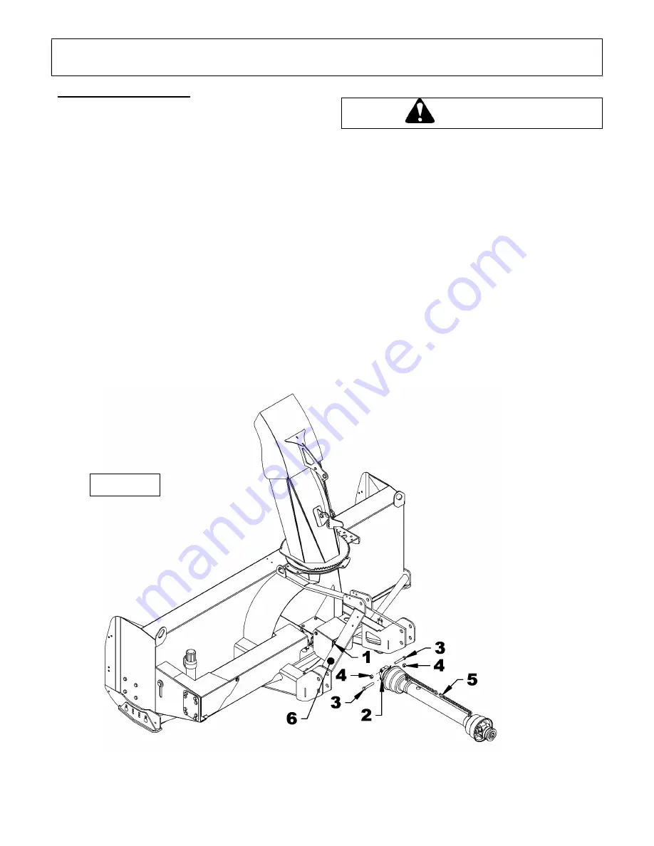
Driveline Installation
1. Figure 6:
Remove the paint from the gearbox
shaft (item 1) and grease if needed. Grease
also the sliding surfaces and yoke (item 2) of
the driveline.
2. Figure 6:
Remove the bolts (item 3) from the
yoke (item 2) and connect the yoke to the
gearbox shaft (item 1). Secure the driveline by
reinstalling the bolts and nuts (items 3-4) in
the order shown
. Tighten all bolts according to
the
Torque Specification Table
at the end of
the manual.
3. Figure 6:
Install the driveline (item 5) on the
tractor shaft.
4. Figure 6:
Attach the safety chain (item 5),
snowblower side, around the right or left hitch
to prevent driveline shield from rotating.
Attach the safety chain, tractor side, to the
tractor appropriate location.
To avoid serious injuries or death: This shaft
rotates at high revolution (RPM). If the quick
release system is not securely locked on the
tractor shaft (a click must be heard) or if the
coupling to the snowblower is not secured
correctly, the driveline can be released with
force which can cause serious injury or
death.
CAUTION
Figure 6
Содержание BLIZZARD B84C-L
Страница 2: ......
Страница 10: ...GENERAL SAFETY INFORMATION 8...
Страница 11: ...GENERAL SAFETY INFORMATION 9 1 Safety stand 2 Secure point for safety stand...
Страница 37: ...PARTS 35 FIG RAD1705006 SNOWBLOWER 84 FRONT...
Страница 39: ...PARTS 37 FIG RAD1705007 SNOWBLOWERS 84 REAR...
Страница 41: ...PARTS 39 FIG RAD1708001 CHUTE WITH DEFLECTOR...
Страница 49: ......
Страница 50: ......
Страница 51: ......


