
58
EN
L
N
PE
5
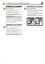
3
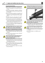
(a)
(b)
(c)
(e)
(d)
(f) (g) (h)
(i)
24
L
N
PE
5
3
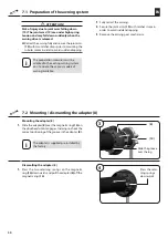
(a)
(b)
(c)
(e)
(d)
(f) (g) (h)
(i)
23
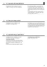
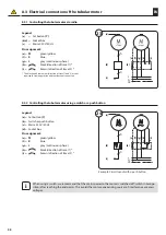
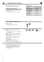
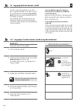
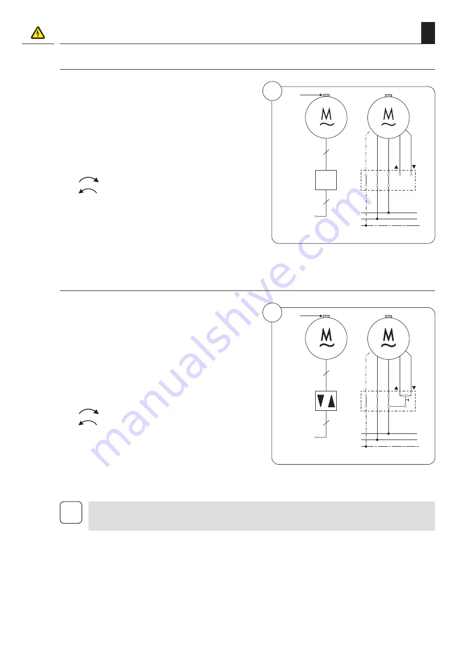
Legend:
(a)
= Set button
(7)
(b)
= Switch or push button
(c)
= Mains 230 V/50 Hz
(d)
= Socket box
Pin assignment:
(e)
=
PE
green/yellow
(f)
=
N
blue
(g)
=
L
grey (continuous phase )
(h)
=
black (direction of travel 1) *
(i)
=
brown (direction of travel 2) *
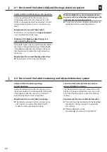
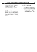
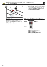
8.3.1 Controlling the tubular motor via radio
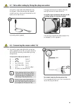
8.3 Electrical connection of the tubular motor
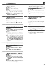
i
When using a switch, we recommend that the mains power to the motor is switched off (switch in zero po-
sition) after reaching the end points. This avoids the motor experiencing sources of interference or excess
voltages.
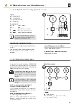
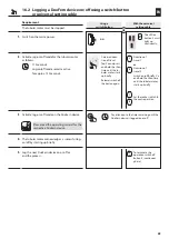
Legend:
(a)
= Set button
(7)
(b/d)
= Socket box
(c)
= Mains 230 V/50 Hz
Pin assignment:
(e)
=
PE
green/yellow
(f)
=
N
blue
(g)
=
L
grey (continuous phase )
(h)
=
black (direction of travel 1) *
(i)
=
brown (direction of travel 2) *
* The black and brown wires (direction of travel 1 and 2) are not
required for radio operation and therefore not connected.
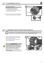
8.3.2 Controlling the tubular motor using a switch or a push button
Example: Circuit layout with a push button


