


Designer’s
Handbook
39
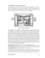
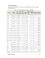
11.
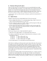
Hardware Bring-Up Procedure
When
a user has designs a new microprocessor system around the Rabbit and carefully
follows
the Rabbit design conventions, it is possible that the system will not boot up when
Dynamic
C is connected to the programming connector. This can happen because of a
design
error or even because of a random hardware defect in the new system. A hardware
procedure
is available to make it easier to debug systematically in such a situation.
A series of steps may be performed in order to diagnosis a problem that keeps Dynamic C
from
booting.
11.1
Initial Checks
Perform
the following checks with the /RESET (pin 37) line tied to ground.
•
With
a voltmeter check for the +5 V or other operating voltage on pins 3,28,53,78,92
and
42. Check for ground on pins 2,27,39,52,77,89.
•
With
an oscilloscope check the 32.768 kHz oscillator on XTALA2 (pin 41). Make sure
that
is is oscillating and that the frequency is correct.
•
With
an oscilloscope check the main system oscillator by observing the signal CLK
(pin
1). With the reset held low this signal should have a frequency one eighth of the
main
crystal or oscillator frequency.
11.2
Diagnostic Test #2
This
test goes through a series of steps repeatedly. The steps are:
1. Apply
the reset for approximately 1/4 second and then release the reset.
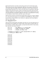
2. In
cold boot send the following sequence of triplet characters to serial port A via the
programming
connector.
80 0E 20
// sets status pin low
80 0E 30
// sets status pin high
80 0E 20
// sets status pin low again
3. Wait
for approximately 1/4 second and then repeat starting at step #1
While
the test is running an oscilloscope can be used to observe the results. The scope can
be
triggered by the reset line going high. It should be possible to observe the data charac-
ters
being transmitted on the RXA pin of the processor or the programming connector. The
status
pin can also be observed at the processor or programming connector. Each byte
transmitted
has 8 data bits preceded by a start bit which is low and followed by a stop bit
which
is high (viewed at the processor or programming connector). The data bits are high
for
1 and low for 0.
The
cold boot mode and the triplets sent are described in Section 3.1 on page 5. Each trip-
let
consists of a 2-byte address and a 1-byte data value. The data value is stored in the
address
specified. The uppermost bit of the 16-bit address is set to one to specify an inter-
nal
I/O write. The remaining 15 bits specify the address. If the write is to memory then the
Содержание 2000
Страница 1: ...Rabbit 2000 Microprocessor Designers Handbook Revision C...
Страница 4: ...Rabbit 2000 Microprocessor...
Страница 6: ...2 Rabbit 2000 Microprocesssor...
Страница 12: ...8 Rabbit 2000 Microprocessor...
Страница 34: ...344 Dynamic C User s Manual...
Страница 36: ...34 Rabbit 2000 Microprocessor...
Страница 44: ...42 Rabbit 2000 Microprocessor...


